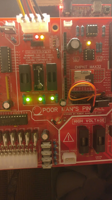
So, I think I finally figured out - or at least the remedy for - why the extra cables were needed.
It was pretty much as I expected and that voltage somehow got reversed in the circuit, and me either knowing too little about electronics or expecting too much from the power supplies. Rookie mistake in assuming the power supply would overpower the other components, but it seems that it doesn't.
Long story short, it would seem that the capacitors I have on the PCB is enough to offset the "power balance" in the board, and by connecting the power lines to the ChipKit's lines I basically hijacked the voltage rectifiers to "heal" the PCB.
By replacing the fuse with a diode (temporarily) all of my problems goes away:
I used diodes to force current this or that way on the board, but forgot/ignored the main lines since I assumed they would be alright coming directly from the PSU.
So now I'm basically trying to find a way to incorporate diodes (Schottky's) in series with each power line. The voltage drop isn't that bad (-0.48V) but still a lot more than I had hoped to achieve. I want to avoid having several boards and something like the below should probably work, but I could also use a P-channel MOSFET as a very low resistance diode.


No comments:
Post a Comment