Showing posts with label Hardware - Lights. Show all posts

Sunday, May 10, 2020

Holy optimizations, Batman!

Spent a "little" time optimizing the code base, along with actually trying to work out the kinks of why optimized mode doesn't work. I'm not all the way there yet, but the results so far are very nice! 

Note: The flickering apparent in both videos is mostly picked up by the camera only and isn't really noticeable IRL, and the refresh rate can be pushed up further. Just keeping it a bit "low" to avoid confusing myself while debugging the rest of the code in case it causes crashes/erratic behavior etc.
For instance - 
Here's a clip of SD-card videos running as fast as possible in the old code. 
Notice the slow motion (faked by frame-skipping previously, removed here). 


And here's the same clip after optimization. 
Compared to the old version, it's a lot smoother and I'm actually running the videos at 40fps here (faster than original 30). Notice the long blank space between the videos, where the old version barely finished rendering the first one when the second one was timed to start. :) 


Some crude counter increments:

Previous one-second count: 28402
New one-second count: 91857

Quite the improvement! 
Very satisfied with the results so far!

In case you didn't notice, I used two simultaneously running SD-animations (background & fx) during the second video. Works great and allows me to spice things up. #thumbsup 
And the cable mess have been mostly corrected now, all lights tested and working. :) 


Monday, May 4, 2020

Rolling with the punches!

What's this... two post within a year? Yes - it actually happened! ;)

Been using my new found determination and time to keep working on the machine, finishing up bits and pieces all over. To start off - flashers, GI and playfield lights are now soldered up and working correctly.

Well, mostly at least.

I ran out of cables so I had to order more.
And I kind of ran out of output ports for the lights, so I'll have to hook up some of them to the AUX-ports I made on the board. (phew). But it's all good! 

1) All lights, switches and solenoids are wired/soldered!
2) It looks very messy, but the cables are actually measured and the "exact" length required.
I ran out of zip-ties, but will of course tie everything neatly when the new arrives.

As for input during menus, I've gone ahead and made the switch "box" that houses the menu buttons. It will be painted and/or covered with a left-over decal, but I'll do that once I've finished the building.

When not in maintenance mode, the red button will lower volume and the green button raise it. Pressing the white button enters maintenance mode. During maintenance mode red/green goes left/right (use can also use flipper buttons), while the white button confirms and start button cancel.

3) The early draft of a control-box inside/behind the coindoor.
Basically - menu buttons and volume etc.

I've also adjusted the syringe to be a little more reliable as a pinball toy and replaced the tiny LED with a proper pinball LED-bulb.

4) I replaced the standard LED with an actual pinball LED-lamp.
No more worrying about accidentally applying too much voltage!


Software-wise I've optimized loading and SD-buffer creation to utilize hardware interrupts for SD-card loading. I've used this a while for DMD rendering, but now I've managed to get it running on the SD-card as well.

So the loops are pretty tight now, which are very nice.
For instance - When sending new data to the DMD I process switches/solenoids etc in the small gap the display needs to stay blank. This is not uncommon among older games which did processing between scanlines (more or less). Works a treat and pretty much doubles the performance.

And now I've done the same for SD-loading, where I basically start loading 512 bytes, and as soon as they're done loading I schedule the next batch and start building the buffer with the 512 bytes just loaded. The unpacking is needed to convert 2K (half-byte per pixel) to a DMD buffer (byte per pixel). The SD card is slower than building the buffer, so that's the reasoning behind not loading the full frame from disk. Previously I built the buffer after all 2K was received, but now I've shaved of a few milliseconds by doing it while "idle". Very nice! 

I've also started the rather tedious task of converting away from Arduino/Chipkit's "String" class. It's ridden with bugs, memory intense and in fact - won't even run when compiled as O3 ("optimize for speed")... There seem to be a problem with the hardware watchdog resetting during optimized compilations, but I can't get my hands around why at the moment. Considering the standard/built-in libraries won't even run properly, I'm not terribly sure my code is the culprit here...

But first, back to the 80's we go; hello, C-string.

Wednesday, December 26, 2018

Cables... oh god. So many cables...

Been busy removing old cables and stripping the playfield from "debris" the last few weeks. It was a big but crucial step in order to get the new wiring neat and functioning properly. 
1) Cutting commenced! It's funny how destroying things always goes faster than building them...

2) Patient is on the operating table.
Straight under a florescent light, there's _finally_ a good work space to work on the machine!

3) Remains from the sockets and switches. The cabling all in all filled a big plastic bag... :|


I found out that I had placed all switch diodes wrong, so I actually redid the switches... twice.

Oh the horror when reconnecting a fully rebuilt pinball table and.... nothing. Haha.

But it's done properly this time, and as an added bonus the wiring is identical to commercial machines now. This means that if I forget how it's built in a few years I can always look up the wiring online - or in the manual I've decided to write for the machine. The manual will keep track of all hardware, parts and positions etc, and will have pictures and "maps" to show each position. I have also started gathering manuals for the actual hardware used on the PCB and table/cabinet. Nothing should have to be guessed or "reinvented" during the next repair. :)

4) Yo, Internet. Welcome to my crib...

I've also miscalculated the amount of cabling necessary now that I've gone full matrix on lights and switches and making sure each switch follows the trunk. So basically I'm 90 meters in and only had enough cables for the switches. :'D

But more cables are on the way, so early next year I'll have the lights and other cables in place!

5) The finished (more or less) wiring for switches! Since I've been using different switches of various makers
I've unfortunately not been able to keep a pro-standard everywhere, hence the "floating diodes" in a couple of places.
I also ran out of shrink tube, which will be used everywhere there's a cable "edge" visible.


The coding was also revamped slightly to accommodate the changes in the switch matrix, and overall it seems rock solid. Of course, it will be tested and retested during game rules programming, but I haven't been able to "trick" the machine from detecting hits now, something that was possible earlier due to the relatively (very) slow switch detection.

Sunday, January 28, 2018

Remembering The Past

Needed the soundboard from the "old system", so I opened up the pinball machine for the first time in a while... And I was actually surprised to see what a mess it was/is! It's a wonder it even worked at all, haha. :D

Anyhow -
It was quite satisfactory to see that where the old setup used tons of different boards, two MCU's and a cabling from hell, the new setup is ultra neat in comparison. And despite having "only" one MCU, the performance is 4x in most cases, but 200x when it comes to I/O. Hardware stability is improved a lot as well! I'm also pleased with the new code library compared to the old, which will make game programming a breeze.

The maintenance mode is always enabled, which gives me detailed input on sounds running, scenes started, sound and input / output etc - so I can see right away if there's a problem. Love it!

1) The old....monstrosity. This is actually HW3.0, if we're counting revisions.
HW4 (current) is seen in the post below, which despite being in development "mode", still looks tons better. 

Thursday, October 12, 2017

ULN2803A!

1) Fully populated board with everything up and running. Since this is my first circuit board ever made
and my first venture into advanced electronics, I'm very proud to see it functioning properly!


Yes!
It was a broken ULN2803A that was the problem with the light matrix.
Very satisfied with that little bit of knowledge, as this now means that all parts of the hardware has been checked and verified. Now it's simply a matter of fine-tuning everything and create, solder and connect the final cabling.

Exiting times to say the least! :D 

Tuesday, September 26, 2017

Turtles....

...are faster than me.

But at least they're not doing a million things at once. Or building pinball machines. :)

Since last I've had some issues with the MCP23S17's, and they didn't want to function properly. I think I got the hang of them now though. There were a couple of issues, for instance;

1) One of the MCP's relied on the Max32 to send an enable signal to it, but it seems the pin can't supply the necessary voltage and/or amperage needed to keep it enabled. I temporarily jumpered it to 3.3V and that solved that. I will probably solder this to the watchdog output instead, since that and the other two MCP's relying on it seem to function properly.

2) The switch matrix MCP displayed the status incorrectly on the DMD. I'm still using a temporary DMD "library" that lets me dot pixels for basic trouble shooting. I forgot to add the clear buffer function, so every draw could only add to the screen and not remove. This fooled me to think that the built in pullups malfunctioned and/or the software for it. I've verified functionality with a LED instead and everything works as intended, and has most likely always done so.

3) I've moved away from all fancy MCP-libraries and communicate directly via SPI, and that probably helped a lot in knowing exactly what's going on. Will encapsulate this into functions optimized for the "thread" handling I've planned for them.

Lastly, I've, err, confirmed that the fuses function properly.
While testing the inputs I did something very wrong (i.e voodoo connecting things) and blew the 5V fuse. It's rated at 3.25A so that's a pretty decent amount of current that was blocked instead of frying other components. 

But at least things are moving forward! :)

Tuesday, July 18, 2017

Get the jig' with it!

Not a "proper" update, really, but I've attached the PCB, screen and PSU to a spare piece of plywood which allows for easier handling and development. All necessary connectors are reachable as well, so I'll be able to hook up I/O and even solenoids to test things as well.

Since I am developing outside the box (no pun intended) this will help a lot to keep things tidy.

1) Piece of scrap plywood with components attached. Not much to say really. ;)

Thursday, July 6, 2017

It's all the mind

The progress as of lately has been mostly theoretical and the new PCB has been untouched.

Been really busy with life in general while the machine has been thoroughly playtested during parties, birthdays and integrity checked by my kids. It holds up, mostly, but there are weird bugs that I believe cannot be fixed in the current state. Weird stuff happens and cross-circuit spikes cause things to trigger wrongfully and what not, and for some reason you can sometimes no longer drain the ball when you're on the second ball. This occurs at random, and when it happens totally unrelated buttons stop working, such as the Start-button, and the debug mode for the lights starts etc. Wiring is alright, but as I wrote, I believe cross-talk or voltage spikes are to blame.

Anyhow;
I'm looking forward to four sweet weeks of uninterrupted work on the machine, which is when the new motherboard will be transplanted. Hopefully everything checks out and I can finish up the new wiring as well. Really looking forward to tidying up everything, getting the new code and video in place and get on with actual game programming!

Thoughts for another day;
Thinking about making the playfield artwork brighter, possibly remaking the artwork. But that'll be done once this playfield has gone fubar.

Sunday, April 30, 2017

"If normal at first, measure again"

So...
The board didn't work.

Or at least it didn't before.

My previous post was a false positive and everything started to behave really weird, with negative voltages and what not, as soon as something was connected and plugged in. The power switch was controlling a MOSFET, which in turn disconnected or connected all power lines to GND. For some reason the current flow was really wack because of this. For instance, inserting a LED in the 5V line really shouldn't reroute power from the 3.3V line and vice versa. This was a real pain to troubleshoot, but after butchering the board quite badly (#sadface) I ultimately found the problem (#happyface).

The solution simple enough - just bypass the MOSFET by shorting the drain and source. I really wish that I'd found this simple solution before massacring all capacitors. Now things are finally working correctly with the exception that I cannot turn power on and off with the switch, as I've hoped to do. But it's a minor issue and was more of a nice touch anyway, as it wouldn't be used in production.

1) Everything's looking dandy! For real, this time...

A major give-away, which I can't believe I overlooked, was that the status light previously didn't light up. It's directly connected to pin 13, so it should have blinked during boot. The fact that it never once did (before) would have told me that current was going the wrong way - or was insufficient. But I was simply assuming that I was shorting stuff when in reality it's perfectly fine to measure where and how I did. The wonders of stress...

Another issue leading to "premature optimization" was that I'm using an old Chipkit, which of course had some pins enabled that are now used for MOSFET control. This lead to having the light rows being always on for instance, but since they turn off during reset of the Chipkit they work perfectly fine.

Lesson learned? Don't put in untested parts in the schematics on the basis that "it should work, right?". The power switch was a last minute addition and a huge pain the Arizona.


Tuesday, April 25, 2017

Capacitors... Crap-acitors?

After investigating I think that the board actually might be working correctly after all (why do I sound surprised?).

A couple of issues -

* I have only tried to power the board via another ChipKit, since I haven't got a spare PSU. The only one I have is in the machine itself.

* The capacitors are "huge" and store a ton of energy compared to it's current consumption, which is more or less nil in its current state. This led me to think that the circuit was powered when not, and also the other way around - turning them on takes a while and is not instant.

* The SD-card reader draws quite a lot of power, and when it was connected (or possibly due to its connection with the ChipKit). Whenever the SD card was inserted, the 3.3V lane "died", i.e all power went to the SD card. As I said, it could also be that the ChipKit is trying to power itself from the SD card data lines etc.

* When attempting to read voltages I must have created a connection with the multimeter and supplying current instead of simply reading it.

So - I removed the SD card (temporarily) and powered up 3.3V and 5V simultaneously with a 3V battery pack. (not ideal, I know). And viola;

1) The connected power lines are active! #celebration
The LED's are protected with resistors for each voltage, so the 5V LED naturally looks dimmer. The green LED's are also diffused instead of clear, and of less brightness naturally than the power and status LED's.


The board look correct and both lines get power. Removing the SD card only instead of the whole connector also works, so there's no short circuit either.

Flipping the power switch to off yields this:
2) Everything is off!
Side note: The yellow capacitor on the SD is not connected to 3.3V and CLK, but 3.3V and GND. It just looks that way. :)

Which is exactly the way it should be - all lines are off!
When putting a LED in the 5V + GND sockets ("unconnected" test-areas) it properly lights up and turn off when supposed to. Only putting power on either line when the switch is off does not power up the LED over +5V + GND, just like it should.

So I'm thinking the capacitors are the main culprit, along with insufficient power to boot the board properly?

I guess the next step would be to arrange a PSU and proper power and take it from there. I'm still taking baby steps since I don't want to fry any components, worst comes to worst. :)

Trouble in paradise!

Still waiting for the final parts... but...

It seems there might be an issue with the power section.
It would seem that current leak from 12/5V into the 3.3V and more or less turn on the circuit even if there's just a single voltage lane (that should be off) active. It could also be that the debug ChipKit I am using, an old broken one, could be outputting current on the power status connection (which will be an input later) enough to open the gate.


As always with electric and digital troubleshooting, the hardest part is usually finding the error. In this case, most likely a well placed diode will remedy the issue. I will look into this tomorrow, but I'm pretty sure it's a minor detail.

On a side note - 
I'm certain the end result will be worth it, and there's really no other way to do it properly than to remove all the old "gunk" and re-do it piece by piece. Properly.


But.
So close, almost there - only to be torn apart again.
It's a bit scary to dismantle the machine...

Monday, April 17, 2017

Quick update from the land of PCB's!

Almost done with the circuit board!

Just the ATX connectors that needs salvaging from other boards and the power sockets that I've forgot (?) to order. Other than that, it should be ready for a check and conversion from old to new.

I'm especially proud of the big capacitor "UPS" for the ChipKit and the accompanying power sense circuit, meaning that the board will run for a few milliseconds after the power disappear, just long enough to save data to the EEPROM and shutdown things neatly. The watchdog will still kill any lingering solenoids, but it won't hurt to properly turn them off.

1) Almost fulled assembled. Sorry for potato quality picture!

Sunday, March 19, 2017

PCB's have arrived!

Got the PCB's today - and I'm very impressed by the work of Seeed Studio!
Superb finish and to the best of my knowledge not low-budget in any way. Despite being half the price of Dirty PCB's "cheap and dirty PCB's", they look stellar.

Now I just have to wait for the rest of the parts to arrive.
Agonizing...


1) PCB's. Turned out even better than I hoped for. Hopefully it's not five giant coasters...

Sunday, February 26, 2017

Order's placed!

Fingers crossed - board is ordered!

But not from DirtyPCB's - from Seeed Studio instead. Half the cost as well, which is nice.
Minimum order was 5 so I'll have to spare in case I mess up!

Something like this will be what I'm getting:

1) Should be rounded corners, but the preview doesn't show. Either this manufacturer doesn't allow it
or the preview doesn't show them. Probably the latter since it allows for quick re-theming of the colors,
leading me to think it's simply a color rectangle slabbed on top. 
I also created and added a small PCB-adapter to push all random left-over pins into a single connector along with 5V, GND, serial and I2C for possible future add-ons. 

Wish me luck!

Monday, February 20, 2017

Putting Boards In Perspective...

Ok, so maybe I've gone a bit "home blind" here.
Just measured the board extremely scientifically by holding up a Max32 in front of the screen.

Turns out the board is a lot more compact than I thought when designing it.  :|

1) It's all in the details. In the fine, fine details.

Soldering this... should be interesting!

Saturday, February 18, 2017

Easy Peasebee.


This one feels pretty much "there", actually.
Just some minor tweaks and a good walkthrough of all pins and connections (and a final testing of each circuit again) - then I'll be ready for ordering!

1) My first PCB ever manufactured! Or designed, rather. Measuring in at 26x15 cm it's more or less the size of two experiment PCB's. Only this time everything fits on one card. 

2) Flip side. Since I'm not perfect I've designed all Chipkit pins to be accessible while it's attached. I've also added a
couple of "experiment" areas for IC's and additional things I may have forgotten or in case I add, stuff breaks etc.
The pads on the ATX connectors that are slightly smaller are unconnected, but I'll solder 'em on for support.

I think it turned out rather nicely actually. Pretty proud if I may say so. Let's just hope it works! ;)
Also... routing by hand beats automatic routing in aesthetics every day!

Thursday, February 16, 2017

Pesebee Rev A!

I've tried and tested all (I think) variations of the planned circuits, and they seem to work perfectly. So I've gone and started with the PCB layout.

1) Simple "everything at once" picture. This is 100% autorouted, so it's not the most aesthetically pleasing routing,
and I'll probably try to route at least the output elements before letting the autorouter fill in the gaps.
I think that the 48V traces needs to be bigger as well, at the moment they're 2.54mm wide.  

2) Since all my sub-boards (Chipkit, SD card, WAV Trigger) are red - and it's a nice color - I'll most likely go with red.
This is taken from another stage in development, so it doesn't match up with the drawing above.

I'm not entirely satisfied with this, and I missed a few items.  It's 23x14 cm large at the moment and probably needs to grow a little to accommodate the larger 48V traces.

So there's probably a few more revisions until I send it to DirtyPCB's for manufacturing. The Diptrace license I got was 500 pins, so it doesn't give me a whole lot of wiggle room - but I'm not complaining; Diptrace is an excellent software and pretty user friendly! :)

Monday, February 13, 2017

Revision Revised

I was wrong about the voltage in the last post.

Turns out I had connected rows and columns wrong (swapped really), so the lights were always on and stuck on the very first row. Doh... 

After a night of frantic coding, I've managed to do something really weird.
With an input voltage of 12V, I get; 12V out. Despite duty cycling at 1:8.
What.

I measured the voltage without anything connected, between P-channel output to N-channel input, it's rock solid at 12V when active. If I put a light there and measure the same way, it's around 1V since the bulb is stealing the rest of the voltage. The light turns on and off as I rotate the active light in software, so it's not constant on either. I am using pull-ups for the P-Channel MOSFET's, but it does feels a bit too good to be true.  :)


1) Chipkit driven by 12V wall wart, 12V out to P-channel TIP107's via the Vin-pin. The meter says 12V, but my senses says it couldn't really be. But it's bright enough to shine through a very dark smoked glass candle thingy.


Thursday, December 1, 2016

Double polarity LED's... who knew?

Oh boi. I'll just say it.
Shame on me - I missed a couple of diodes.

The bumpers and flashers were still "unprotected" and on top of that, the LED's I had installed were double polarity meaning they worked in both directions....  Who could have known, right?

The good news are that lights are now working somewhat properly (we'll get to that) and I've updated the main board with the correct lights and what not. This means I'm kinda back where I was before recreating the light board. And that's a good thing! I've also fixed sound and music, which had a few bugs that has stayed uncorrected since moving to the new system and board. Tried a couple of quick games too. 8-)


The bad news is that there is a slight flickering when a couple of lights are active at the same time. This flickering occurs on the light board itself as well, so it may be due to lack of power in the board or shift registers. I'm currently using a row/col based approach, which lights up to 12 lights per channel. I will try converting to col/row so that each row only ever power a single light at once. Hopefully that solves things.
 
I've also noticed that the servo handling the target bank was dead.
So I replaced it, only to find out that that servo too died after a few on/off's. The servos are beefy ones and are moving up to 5kgs, which is more than enough for the purpose, but somehow they die anyway. This last one has frozen in place, unable to turn, but it sounds like it's working. I'll have to investigate this further.

On top of that, the captive ball lane captures balls despite having no ball lock. The irony...

Code revision on the game will have to wait until the servo is corrected, as well as the captive lane.

But yeah, progress! \m/  

Sunday, October 30, 2016

It's not me, it's.... something else.

So, got my dirty hands on the light board and re-did the whole "extra board" thing. It still looks like crap, but at least now it doesn't glitch or have connectors that risk failing.

Then I realized, by accident really, that there was no ghosting to speak of in the board.
There wasn't even a problem with the board itself, besides the glitchy MOSFET, that is.
The problem is that somehow, don't ask me how, current is traveling back through the light grid/matrix and "triggers" other ports.

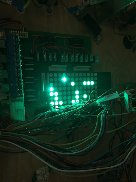
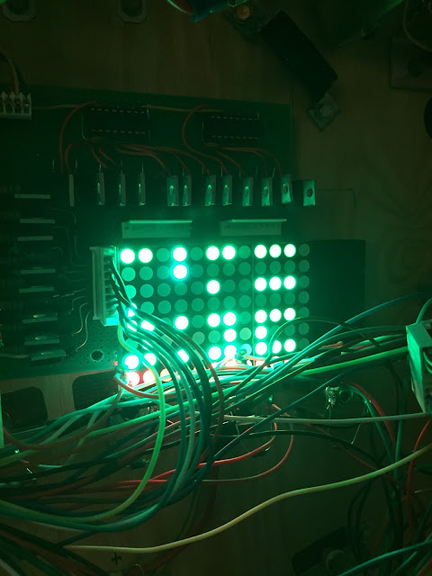
1) Light board only. No light cables or playfield connected. The camera had a rough time trying to photograph this, but everything looks just fine IRL. Crisp and sharp lighting and most importantly - no ghosting.

2) The very same light setup except that the power connector to the playfield has been connected as well. Behold - The mother of all double triggering, ghosting, annoying and downright irritating setup is created.
I don't know for sure at this point why this is happening, and it's rather hard to measure with a multimeter. Since it's using 3 MOSFET's enabled per active light it's also extremely/"impossible" to troubleshoot outside the cabinet. But here's what I got so far -

Everything is working perfectly with no extra cables attached.
Since the board has diodes from each MOSFET to the power lines and that the LED matrix on the lightboard is just that - LED's - current must be coming back through the very same power lines.
Unless I'm measuring wrongly, I'm also reading negative voltages on the ports that should be off.

That means the board _should_ work perfectly fine and that the problem should indeed be in the light matrix/series on the playfield itself.

Could I have connected something wrongfully? Possibly.
But still, I don't understand why it should be that - I got diodes installed on each lamp. So current can only flow in one direction, unless I made a mistake somewhere. But with everything attached there's just too many variables to investigate. Have to narrow down the search area...
I'll most likely troubleshoot this in a rather naive way -
By disconnecting all power cables from the playfield and adding them back one at a time (possibly with a diode as well).