Saturday, February 27, 2021

Achilles, Agony and Ecstasy In Eight Parts

So, I decided to fix the power rails. 

First I removed the old fuses.... 


...built a board to host all three PSU's. 

Yes, three. The scratches on the 12V line is me severing that line to allow me to use a 24V PSU instead of 12V. This line also provided power to the Chipkit, so Chipkit got its own jack now too. Real pinball machines strobe their light matrix with 18V, so 24V should provide more vibrant lights and flashers. 


Black is the new ...black, baby! 


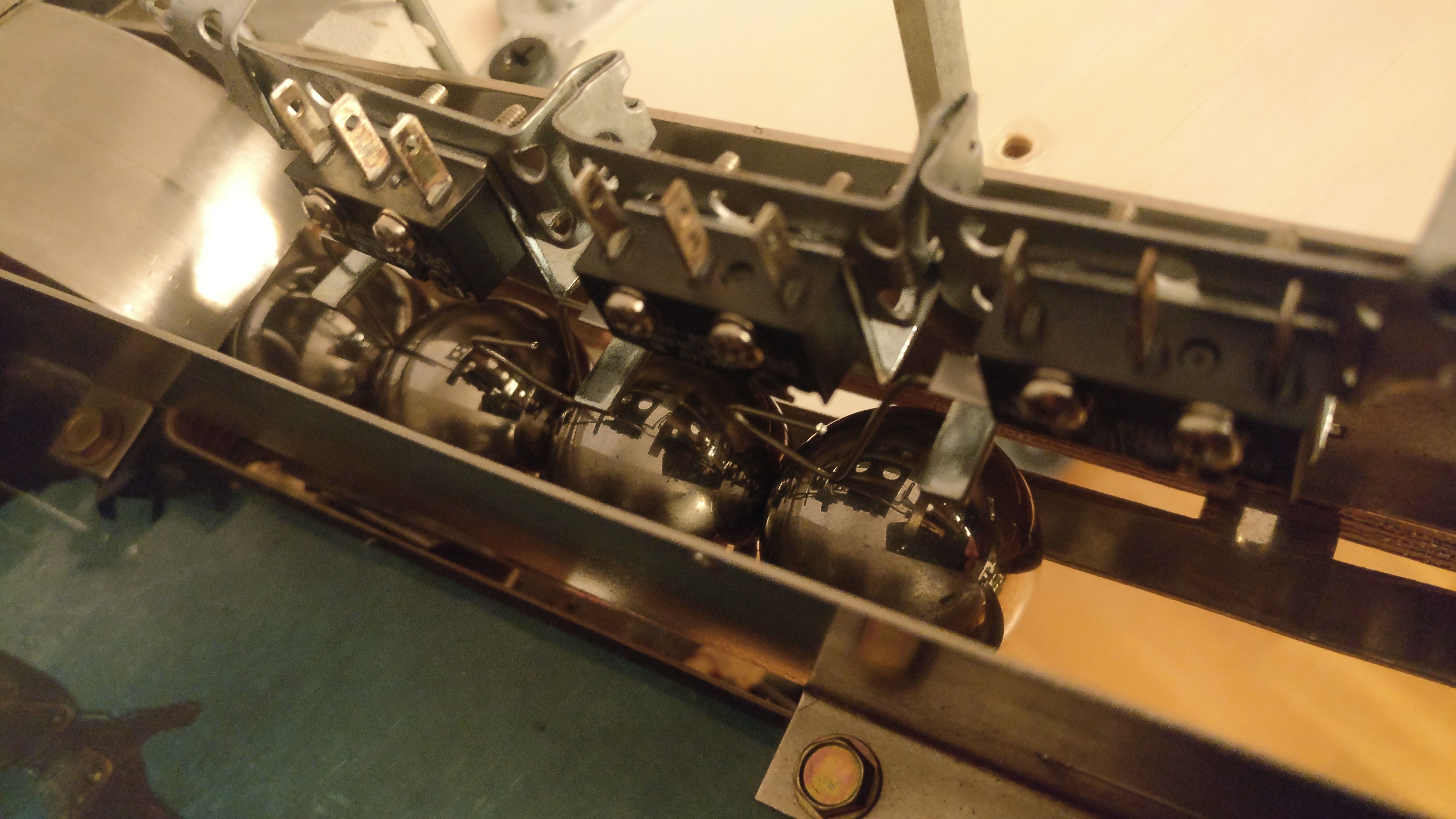
Prepared the little power circuit.... 


And removed / accidentally messed the traces when removing a capacitor (more about that later)...


....but finally got everything in place! 


Nice! Looking almost as if was part of the plan. 


The board lights up! 


But, did it work? 

Of course not. 


It's infuriating and fascinating how something can be tested and tested again, and work perfectly in a controlled environment - and yet fail miserably in the real world. Even when loosing my cool and removing a few of the caps (and doing a hack-job at it too....) it wouldn't work. 

So here's Mr Cable once again. At least it's before the fuse this time, although I'm not sure that'll help. 
The big downside is that I cannot start the PSU after I've inserted the USB-cable, so I have to power up the machine/board - then - plug in the USB-cable, or only use the USB-cable. 


To be fair, it does work without the extra cable - eventually. After a few attempts and the power has stabilized it's possible to re-init the IC's that fail and they'll work. But it's highly unreliable and even when removing the 5V fuse, the LED still lights up, so power is sourced from somewhere. I don't really know where the power creeping is coming from - it feels unsettling to leave it without the extra cable.

 Anyhow, win some, lose some. Story of this build. :) 


Wednesday, February 24, 2021

MOSFET's... You will never find a more wretched hive of scum and villainy.

So - apparently there's a thing called an ideal diode that can be created using MOSFET's instead

For instance, comparing two circuits built in Falstad


1) Diodes in series with the power lines, compared to P-Channel MOSFET's (+ protective diodes and resistors)


Even using default values (there are better - and worse - components out there) the P-Channel MOSFET version provides a voltage closer to the source and provide the same features. This MOSFET version should be possible to use in my "vertical fuse holder"-design as well, but require a bit more components and "not as clean setup".

I will have to do some breadboard tests to see which one to use as both will work, but it's nice to keep as much power as possible so I'm leaning towards using the MOSFET one at the moment... 

Saturday, February 20, 2021

Beam me up, Schottky!

So, I think I finally figured out - or at least the remedy for - why the extra cables were needed. 

It was pretty much as I expected and that voltage somehow got reversed in the circuit, and me either knowing too little about electronics or expecting too much from the power supplies. Rookie mistake in assuming the power supply would overpower the other components, but it seems that it doesn't. 

Long story short, it would seem that the capacitors I have on the PCB is enough to offset the "power balance" in the board, and by connecting the power lines to the ChipKit's lines I basically hijacked the voltage rectifiers to "heal" the PCB. 

By replacing the fuse with a diode (temporarily) all of my problems goes away: 

1) It ain't safe and it's not pretty, but proof is proof. 
Notice the disconnected +3V3 and +5V cables. 

Oh, fun fact:
Turns out that the +3V3 cable wasn't really needed.
I had damaged the trace on the board while removing the capacitor
in my first feeble attempt to solve the power problem a year ago or so. 


I used diodes to force current this or that way on the board, but forgot/ignored the main lines since I assumed they would be alright coming directly from the PSU. 

So now I'm basically trying to find a way to incorporate diodes (Schottky's) in series with each power line. The voltage drop isn't that bad (-0.48V) but still a lot more than I had hoped to achieve. I want to avoid having several boards and something like the below should probably work, but I could also use a P-channel MOSFET as a very low resistance diode. 


But I'm going to try to use a setup similar to the one at the top in the above image, where the diode would be standing up and connect to a vertical mounted fuse cylinder instead. It should work, and it seems there's enough space. Would be nice to get rid of this pesky power problem once and for all. 

But we'll see. 

Friday, February 19, 2021

Daily motivation!


1) Steinman got his sign back! (I misplaced it two years ago... :') ) 


2) I really like this corner. The two-way quadtych-switch is pretty cool. 
Although I am toying with the idea of making it open/close via servo... 


3) Got the new ball through in place, although I'm still waiting for my new soldering iron.
But switches tested and works fine.  


4) Someone asked me why pinball machines are so big... Thing is - the playfield is pretty much
the same size under the board as above, so there's not a whole lot of empty space inside actually. 


5) The plasmid saucer. I have not settled on the final behaviour yet, since it depends
on how hard it is to "backhand" the ball into this corner. But we'll see.  


6) Originally a captive ball, then thought to be a ball lock - and now "just" a lane. 
Kill your darlings, they say. Anyhow - it's a tricky shot so it should feel quite nice when hit. 


7) The upper playfield as it stands today. Looks pretty good, imho! 


8) A full overview of the playfield 2021.

I set out to make it look commercially made, and I believe I've
accomplished that as far as the playfield goes. Just need to make
sure the gameplay and rules are up to par!  

I really like that I've been able to make the whole 'miniature wonderland'-feeling
I wanted from a pinball. I've always enjoyed miniatures and the glimpse into another world
you can achieve with them. Can't wait until I get to play the first actual game! :)  


Wednesday, February 17, 2021

Jinxed-Schminxed ...

So, yeah... 

"unless - epic ninjas forbid - connecting the solenoids mess something up"

Guess what? 

I had messed up.

Almost burnt down the board since +48V pretty much forced all the gates open.

1) That mini-heartattack when you apply power, "all is well?" and suddenly smoke rises from the board
while the solenoids are going tick-tick-tick... 


I had pull-down resistors on the gates, but since the +48V and +5V didn't have a common ground the gates were essentially floating anyway. (Thanks for the help again, Majenko!) It didn't show up in earlier tests since I used +5V and ground from the board itself to test the circuit, but when the other supply was used it didn't work correctly. For some reason I assumed the high voltage power could be completely separated - and I realize how naive that was in retrospect. 

The fix was easy enough after actually finding the error, just a cable between GND & GND and Bob's your uncle...

...until I realized that I've somehow completely forgot to add pull-down resistors to pretty much all other MOSFET's on the board. *sigh*. So I'll have to fix that by soldering on resistors between gate and source even though that probably means putting components on the backside, but...

... my soldering iron broke down.

 
And now I play the waiting game with the Swedish postal service once again.
This build is cursed, I shit you not... 

But besides doing two lame n00bzor 2000-mistakes (which I didn't do when designing the circuits on breadboard, mind you) the machine can now flip balls.

And that's pretty dope. 

I also got two potentiometers in place to (in theory) help me dial in the opto's to only react to the IR-LED and not (as much from) the sun, for those rare Swedish summer days. 

2) Dialed In! ;) 
JJP are pushing out some high quality boards these days. STERN needs to up their game, imho... 


Footnote: 

I've been hunting a few bugs that are seemingly random - perhaps they too are caused by the floating pins. Would also be interesting to see if the +5V and +3.3V cables are required once all floating pins are properly grounded.  


Monday, February 15, 2021

The devil's in the details... (is he really that small, though?)

Spent the last weeks writing rules and preparing each game mode with music, sound effects and overall flow of the game. It's getting quite complex (as it should be) considering the development time on the machine, hehe. Since I don't have room for more than one pin, I guess it won't hurt having a deep rule set either. Doing my best to stay true to the game(s) while having a bit of artistic freedom with each event, I think I've got a good chunk of fun and must-have elements in there. We shall see.  

I've corrected a couple of wrongfully connected switches and finally bit the bullet and replaced a couple of older cables for the targetbank that I left with the wrong wire colors - as I obviously connected them wrong anyway. All good now, though! 

I've also added a few more decorations and touch ups on the playfield - without further ado:

1) Mask for the Quadtych. The area was missing something and once the mask was in 
place the whole area did, as Sander Cohen said, come together.
 

2) Spinner "topper". There's a few iconic places in Rapture, so it 
felt nice to have them presented on the playfield as well. 

3) Party mask for the New Year's Eve ...ahem.. party. 

4) The "hidden" doll lane has been upgraded with a physical doll figurine. It's adorable. 
Might get a proper one for my kids, haha. 

5) Although not necessarily in the "correct" spot, the lower right area felt a bit bare - until now. 
The original plan was to have this cage around the center VUK, but it looks crowded enough already. 


So, all in all - things are moving along and unless - epic ninjas forbid - connecting the solenoids mess something up, I'm looking at a fully playable machine in the very near future!