Showing posts with label Electrics. Show all posts

Saturday, February 27, 2021

Achilles, Agony and Ecstasy In Eight Parts

So, I decided to fix the power rails. 

First I removed the old fuses.... 


...built a board to host all three PSU's. 

Yes, three. The scratches on the 12V line is me severing that line to allow me to use a 24V PSU instead of 12V. This line also provided power to the Chipkit, so Chipkit got its own jack now too. Real pinball machines strobe their light matrix with 18V, so 24V should provide more vibrant lights and flashers. 


Black is the new ...black, baby! 


Prepared the little power circuit.... 


And removed / accidentally messed the traces when removing a capacitor (more about that later)...


....but finally got everything in place! 


Nice! Looking almost as if was part of the plan. 


The board lights up! 


But, did it work? 

Of course not. 


It's infuriating and fascinating how something can be tested and tested again, and work perfectly in a controlled environment - and yet fail miserably in the real world. Even when loosing my cool and removing a few of the caps (and doing a hack-job at it too....) it wouldn't work. 

So here's Mr Cable once again. At least it's before the fuse this time, although I'm not sure that'll help. 
The big downside is that I cannot start the PSU after I've inserted the USB-cable, so I have to power up the machine/board - then - plug in the USB-cable, or only use the USB-cable. 


To be fair, it does work without the extra cable - eventually. After a few attempts and the power has stabilized it's possible to re-init the IC's that fail and they'll work. But it's highly unreliable and even when removing the 5V fuse, the LED still lights up, so power is sourced from somewhere. I don't really know where the power creeping is coming from - it feels unsettling to leave it without the extra cable.

 Anyhow, win some, lose some. Story of this build. :) 


Wednesday, February 24, 2021

MOSFET's... You will never find a more wretched hive of scum and villainy.

So - apparently there's a thing called an ideal diode that can be created using MOSFET's instead

For instance, comparing two circuits built in Falstad


1) Diodes in series with the power lines, compared to P-Channel MOSFET's (+ protective diodes and resistors)


Even using default values (there are better - and worse - components out there) the P-Channel MOSFET version provides a voltage closer to the source and provide the same features. This MOSFET version should be possible to use in my "vertical fuse holder"-design as well, but require a bit more components and "not as clean setup".

I will have to do some breadboard tests to see which one to use as both will work, but it's nice to keep as much power as possible so I'm leaning towards using the MOSFET one at the moment... 

Saturday, February 20, 2021

Beam me up, Schottky!

So, I think I finally figured out - or at least the remedy for - why the extra cables were needed. 

It was pretty much as I expected and that voltage somehow got reversed in the circuit, and me either knowing too little about electronics or expecting too much from the power supplies. Rookie mistake in assuming the power supply would overpower the other components, but it seems that it doesn't. 

Long story short, it would seem that the capacitors I have on the PCB is enough to offset the "power balance" in the board, and by connecting the power lines to the ChipKit's lines I basically hijacked the voltage rectifiers to "heal" the PCB. 

By replacing the fuse with a diode (temporarily) all of my problems goes away: 

1) It ain't safe and it's not pretty, but proof is proof. 
Notice the disconnected +3V3 and +5V cables. 

Oh, fun fact:
Turns out that the +3V3 cable wasn't really needed.
I had damaged the trace on the board while removing the capacitor
in my first feeble attempt to solve the power problem a year ago or so. 


I used diodes to force current this or that way on the board, but forgot/ignored the main lines since I assumed they would be alright coming directly from the PSU. 

So now I'm basically trying to find a way to incorporate diodes (Schottky's) in series with each power line. The voltage drop isn't that bad (-0.48V) but still a lot more than I had hoped to achieve. I want to avoid having several boards and something like the below should probably work, but I could also use a P-channel MOSFET as a very low resistance diode. 


But I'm going to try to use a setup similar to the one at the top in the above image, where the diode would be standing up and connect to a vertical mounted fuse cylinder instead. It should work, and it seems there's enough space. Would be nice to get rid of this pesky power problem once and for all. 

But we'll see. 

Wednesday, February 17, 2021

Jinxed-Schminxed ...

So, yeah... 

"unless - epic ninjas forbid - connecting the solenoids mess something up"

Guess what? 

I had messed up.

Almost burnt down the board since +48V pretty much forced all the gates open.

1) That mini-heartattack when you apply power, "all is well?" and suddenly smoke rises from the board
while the solenoids are going tick-tick-tick... 


I had pull-down resistors on the gates, but since the +48V and +5V didn't have a common ground the gates were essentially floating anyway. (Thanks for the help again, Majenko!) It didn't show up in earlier tests since I used +5V and ground from the board itself to test the circuit, but when the other supply was used it didn't work correctly. For some reason I assumed the high voltage power could be completely separated - and I realize how naive that was in retrospect. 

The fix was easy enough after actually finding the error, just a cable between GND & GND and Bob's your uncle...

...until I realized that I've somehow completely forgot to add pull-down resistors to pretty much all other MOSFET's on the board. *sigh*. So I'll have to fix that by soldering on resistors between gate and source even though that probably means putting components on the backside, but...

... my soldering iron broke down.

 
And now I play the waiting game with the Swedish postal service once again.
This build is cursed, I shit you not... 

But besides doing two lame n00bzor 2000-mistakes (which I didn't do when designing the circuits on breadboard, mind you) the machine can now flip balls.

And that's pretty dope. 

I also got two potentiometers in place to (in theory) help me dial in the opto's to only react to the IR-LED and not (as much from) the sun, for those rare Swedish summer days. 

2) Dialed In! ;) 
JJP are pushing out some high quality boards these days. STERN needs to up their game, imho... 


Footnote: 

I've been hunting a few bugs that are seemingly random - perhaps they too are caused by the floating pins. Would also be interesting to see if the +5V and +3.3V cables are required once all floating pins are properly grounded.  


Thursday, January 28, 2021

I Dream In Infrared...

 F**king finally - opto's are online! 

Pardon the french, but I've been troubleshooting the optos for 6+ months without success, and yesterday the solution came to me lying half-awake in bed... It's stupidly simple, has a few downsides - but it works. 

After a few months of this...

1) Breadboard horror...


I realized (but not sure why) there was no power reaching the +3.3V line that powers the opto's. Come to think of it, pretty much all +3.3V devices are powered by the Chipkit already... hmm hmm. 
Turns out it was easier to create a new circuit on a breadboard and use a regular remote to trigger the IR receiver. This allowed me to see exactly what worked, and I could then apply the same method of troubleshooting on the board itself. 

2) Dusty horror....

Anyhow - I suspect a grounding issue (remember way back when I had problems with the +5V line not functioning correctly, or rather some of the MCP23S17 IC's would not work) so I simply took the same approach here. Basically, allowing the Chipkit to force the current the right way, since I suspect they're better at designing PCB's than I... 


And sure enough - we got opto's. 


3-4) Opto off and on. Tried and tested in the VUK, so it works
properly with a ball too and not just some giant hand covering it up.


Bloody brilliant! 

Pretty happy that I didn't had to make any (more) changes to the PCB and/or create external circuitry. This was also the last remaining hardware that needed to be solved, so onwards to creating the actual game!


Still here? 

What do you mean 'downsides'?


Well, yes. 

This change has pretty much rendered the fuses on the +3.3V and +5V lines completely useless as power will be drawn from the Chipkit (also) regardless. I have moved the screen to it's own power line now though, so worst comes to worst - only a few MCP's will burn to a crisp in case of failure. 
I hope. 


Monday, January 25, 2021

Operation Mother

So - finally got my greasy fingers around properly installing the motherboard inside the machine.

Still haven't got my opto's to work but at this moment I'll have to live without them. Will need to debug the circuit and possibly rebuild it separately in the future. 

Like most of the work on this build it's a bit of "one step forward, two steps back" since I was only going to screw the board to the backing plate. But... I forgot that the backing plate was made out of cheap fiber board so screws won't work - and - of course the cables didn't reach the intended position for the board.


So I did what any hobby engineer with(out?) self respect would have done; I cut a big hole inside the frame of the head.

This worked alright, but due to the placement of the intended cut everything turned out a bit crooked. Not that it matters much, since now it's done. But I know my future self will grin at this during any maintenance session, haha...

"Fun fact" - while checking out the playfield, it turns out most of the rubbers have cracked and need replacements. Again. But I guess I kind of was prepared for that and it'll have to wait until the game logic / game rules are completed and the machine is closed up properly.


Other than a few mishaps; the board is now installed and I didn't break anything in the process!


Installed and ready to be developed!

P.S, ignore the double vision display, there's
a small gap between the display and the panel at the moment. 


Monday, May 4, 2020

Rolling with the punches!

What's this... two post within a year? Yes - it actually happened! ;)

Been using my new found determination and time to keep working on the machine, finishing up bits and pieces all over. To start off - flashers, GI and playfield lights are now soldered up and working correctly.

Well, mostly at least.

I ran out of cables so I had to order more.
And I kind of ran out of output ports for the lights, so I'll have to hook up some of them to the AUX-ports I made on the board. (phew). But it's all good! 

1) All lights, switches and solenoids are wired/soldered!
2) It looks very messy, but the cables are actually measured and the "exact" length required.
I ran out of zip-ties, but will of course tie everything neatly when the new arrives.

As for input during menus, I've gone ahead and made the switch "box" that houses the menu buttons. It will be painted and/or covered with a left-over decal, but I'll do that once I've finished the building.

When not in maintenance mode, the red button will lower volume and the green button raise it. Pressing the white button enters maintenance mode. During maintenance mode red/green goes left/right (use can also use flipper buttons), while the white button confirms and start button cancel.

3) The early draft of a control-box inside/behind the coindoor.
Basically - menu buttons and volume etc.

I've also adjusted the syringe to be a little more reliable as a pinball toy and replaced the tiny LED with a proper pinball LED-bulb.

4) I replaced the standard LED with an actual pinball LED-lamp.
No more worrying about accidentally applying too much voltage!


Software-wise I've optimized loading and SD-buffer creation to utilize hardware interrupts for SD-card loading. I've used this a while for DMD rendering, but now I've managed to get it running on the SD-card as well.

So the loops are pretty tight now, which are very nice.
For instance - When sending new data to the DMD I process switches/solenoids etc in the small gap the display needs to stay blank. This is not uncommon among older games which did processing between scanlines (more or less). Works a treat and pretty much doubles the performance.

And now I've done the same for SD-loading, where I basically start loading 512 bytes, and as soon as they're done loading I schedule the next batch and start building the buffer with the 512 bytes just loaded. The unpacking is needed to convert 2K (half-byte per pixel) to a DMD buffer (byte per pixel). The SD card is slower than building the buffer, so that's the reasoning behind not loading the full frame from disk. Previously I built the buffer after all 2K was received, but now I've shaved of a few milliseconds by doing it while "idle". Very nice! 

I've also started the rather tedious task of converting away from Arduino/Chipkit's "String" class. It's ridden with bugs, memory intense and in fact - won't even run when compiled as O3 ("optimize for speed")... There seem to be a problem with the hardware watchdog resetting during optimized compilations, but I can't get my hands around why at the moment. Considering the standard/built-in libraries won't even run properly, I'm not terribly sure my code is the culprit here...

But first, back to the 80's we go; hello, C-string.

Monday, April 20, 2020

A Ferrari-style pit stop!

Got around to do a little tinker on the board the other day!

* audience cheers *

First - had to recreate the development environment on my laptop. Took a little while, but well worth it in the end. And, naturally, the SD card for audio (and the reader) had given up and didn't work. (...sigh).  A purchase of a new reader and a format later solved that. No big deal. But annoying.


Still a bit of wiring to do, but slowly getting there!
Switches, flashers and global illumination is now done, and with a little luck I'm done with the playfield lights in the coming days (or so).


I knew about this before, but I may have to increase voltage for the lights. Currently 5V is a bit on the low side, as lights are quite dim. To avoid using a lot of constant power I also duty cycle the GI, so I figure 12V would be ideal here.

Luckily; there's not a whole lot that needs to be done - either cut the 5V traces and connect the existing 12V line, or move the drive cables to a 12V port on the board. This can be done "any time" so if the board feels too dim during actual play I'll adjust accordingly. :)

Stay safe!


Wednesday, December 26, 2018

Cables... oh god. So many cables...

Been busy removing old cables and stripping the playfield from "debris" the last few weeks. It was a big but crucial step in order to get the new wiring neat and functioning properly. 
1) Cutting commenced! It's funny how destroying things always goes faster than building them...

2) Patient is on the operating table.
Straight under a florescent light, there's _finally_ a good work space to work on the machine!

3) Remains from the sockets and switches. The cabling all in all filled a big plastic bag... :|


I found out that I had placed all switch diodes wrong, so I actually redid the switches... twice.

Oh the horror when reconnecting a fully rebuilt pinball table and.... nothing. Haha.

But it's done properly this time, and as an added bonus the wiring is identical to commercial machines now. This means that if I forget how it's built in a few years I can always look up the wiring online - or in the manual I've decided to write for the machine. The manual will keep track of all hardware, parts and positions etc, and will have pictures and "maps" to show each position. I have also started gathering manuals for the actual hardware used on the PCB and table/cabinet. Nothing should have to be guessed or "reinvented" during the next repair. :)

4) Yo, Internet. Welcome to my crib...

I've also miscalculated the amount of cabling necessary now that I've gone full matrix on lights and switches and making sure each switch follows the trunk. So basically I'm 90 meters in and only had enough cables for the switches. :'D

But more cables are on the way, so early next year I'll have the lights and other cables in place!

5) The finished (more or less) wiring for switches! Since I've been using different switches of various makers
I've unfortunately not been able to keep a pro-standard everywhere, hence the "floating diodes" in a couple of places.
I also ran out of shrink tube, which will be used everywhere there's a cable "edge" visible.


The coding was also revamped slightly to accommodate the changes in the switch matrix, and overall it seems rock solid. Of course, it will be tested and retested during game rules programming, but I haven't been able to "trick" the machine from detecting hits now, something that was possible earlier due to the relatively (very) slow switch detection.

Sunday, January 28, 2018

Remembering The Past

Needed the soundboard from the "old system", so I opened up the pinball machine for the first time in a while... And I was actually surprised to see what a mess it was/is! It's a wonder it even worked at all, haha. :D

Anyhow -
It was quite satisfactory to see that where the old setup used tons of different boards, two MCU's and a cabling from hell, the new setup is ultra neat in comparison. And despite having "only" one MCU, the performance is 4x in most cases, but 200x when it comes to I/O. Hardware stability is improved a lot as well! I'm also pleased with the new code library compared to the old, which will make game programming a breeze.

The maintenance mode is always enabled, which gives me detailed input on sounds running, scenes started, sound and input / output etc - so I can see right away if there's a problem. Love it!

1) The old....monstrosity. This is actually HW3.0, if we're counting revisions.
HW4 (current) is seen in the post below, which despite being in development "mode", still looks tons better. 

Tuesday, July 18, 2017

Get the jig' with it!

Not a "proper" update, really, but I've attached the PCB, screen and PSU to a spare piece of plywood which allows for easier handling and development. All necessary connectors are reachable as well, so I'll be able to hook up I/O and even solenoids to test things as well.

Since I am developing outside the box (no pun intended) this will help a lot to keep things tidy.

1) Piece of scrap plywood with components attached. Not much to say really. ;)

Monday, July 17, 2017

Pixels be rollin'...

It is with immense satisfaction the first few pixels has been drawn with the new motherboard!

Everything is very basic and the frame is currently hardcoded in 8 shades, but runs well in 16 as well (it's slightly difficult to see without having a proper image though). But it is running the new render routine with interrupt transfers and as a CoreTimer service.

1) Motherboard and DMD, sitting in a tree... The "pulsing" effect on top and bottom rows are simply
8 different shades being drawn. The timing of each color has not yet been adjusted and the screen overlay
is not in place either, which dims pixels and thus make each shade more pronounced.


I'll have to redo the main project file as well, as the one I did the PCB-tests on no longer works. I don't know why and haven't really investigated - now I can implement each section properly and without any guess work instead.

Next I'll get some basic DMD functionality in place before going on to other components.

Thursday, July 6, 2017

It's all the mind

The progress as of lately has been mostly theoretical and the new PCB has been untouched.

Been really busy with life in general while the machine has been thoroughly playtested during parties, birthdays and integrity checked by my kids. It holds up, mostly, but there are weird bugs that I believe cannot be fixed in the current state. Weird stuff happens and cross-circuit spikes cause things to trigger wrongfully and what not, and for some reason you can sometimes no longer drain the ball when you're on the second ball. This occurs at random, and when it happens totally unrelated buttons stop working, such as the Start-button, and the debug mode for the lights starts etc. Wiring is alright, but as I wrote, I believe cross-talk or voltage spikes are to blame.

Anyhow;
I'm looking forward to four sweet weeks of uninterrupted work on the machine, which is when the new motherboard will be transplanted. Hopefully everything checks out and I can finish up the new wiring as well. Really looking forward to tidying up everything, getting the new code and video in place and get on with actual game programming!

Thoughts for another day;
Thinking about making the playfield artwork brighter, possibly remaking the artwork. But that'll be done once this playfield has gone fubar.

Sunday, April 30, 2017

"If normal at first, measure again"

So...
The board didn't work.

Or at least it didn't before.

My previous post was a false positive and everything started to behave really weird, with negative voltages and what not, as soon as something was connected and plugged in. The power switch was controlling a MOSFET, which in turn disconnected or connected all power lines to GND. For some reason the current flow was really wack because of this. For instance, inserting a LED in the 5V line really shouldn't reroute power from the 3.3V line and vice versa. This was a real pain to troubleshoot, but after butchering the board quite badly (#sadface) I ultimately found the problem (#happyface).

The solution simple enough - just bypass the MOSFET by shorting the drain and source. I really wish that I'd found this simple solution before massacring all capacitors. Now things are finally working correctly with the exception that I cannot turn power on and off with the switch, as I've hoped to do. But it's a minor issue and was more of a nice touch anyway, as it wouldn't be used in production.

1) Everything's looking dandy! For real, this time...

A major give-away, which I can't believe I overlooked, was that the status light previously didn't light up. It's directly connected to pin 13, so it should have blinked during boot. The fact that it never once did (before) would have told me that current was going the wrong way - or was insufficient. But I was simply assuming that I was shorting stuff when in reality it's perfectly fine to measure where and how I did. The wonders of stress...

Another issue leading to "premature optimization" was that I'm using an old Chipkit, which of course had some pins enabled that are now used for MOSFET control. This lead to having the light rows being always on for instance, but since they turn off during reset of the Chipkit they work perfectly fine.

Lesson learned? Don't put in untested parts in the schematics on the basis that "it should work, right?". The power switch was a last minute addition and a huge pain the Arizona.


Monday, April 17, 2017

Quick update from the land of PCB's!

Almost done with the circuit board!

Just the ATX connectors that needs salvaging from other boards and the power sockets that I've forgot (?) to order. Other than that, it should be ready for a check and conversion from old to new.

I'm especially proud of the big capacitor "UPS" for the ChipKit and the accompanying power sense circuit, meaning that the board will run for a few milliseconds after the power disappear, just long enough to save data to the EEPROM and shutdown things neatly. The watchdog will still kill any lingering solenoids, but it won't hurt to properly turn them off.

1) Almost fulled assembled. Sorry for potato quality picture!

Sunday, March 19, 2017

PCB's have arrived!

Got the PCB's today - and I'm very impressed by the work of Seeed Studio!
Superb finish and to the best of my knowledge not low-budget in any way. Despite being half the price of Dirty PCB's "cheap and dirty PCB's", they look stellar.

Now I just have to wait for the rest of the parts to arrive.
Agonizing...


1) PCB's. Turned out even better than I hoped for. Hopefully it's not five giant coasters...

Saturday, February 18, 2017

Easy Peasebee.


This one feels pretty much "there", actually.
Just some minor tweaks and a good walkthrough of all pins and connections (and a final testing of each circuit again) - then I'll be ready for ordering!

1) My first PCB ever manufactured! Or designed, rather. Measuring in at 26x15 cm it's more or less the size of two experiment PCB's. Only this time everything fits on one card. 

2) Flip side. Since I'm not perfect I've designed all Chipkit pins to be accessible while it's attached. I've also added a
couple of "experiment" areas for IC's and additional things I may have forgotten or in case I add, stuff breaks etc.
The pads on the ATX connectors that are slightly smaller are unconnected, but I'll solder 'em on for support.

I think it turned out rather nicely actually. Pretty proud if I may say so. Let's just hope it works! ;)
Also... routing by hand beats automatic routing in aesthetics every day!

Thursday, February 16, 2017

Pesebee Rev A!

I've tried and tested all (I think) variations of the planned circuits, and they seem to work perfectly. So I've gone and started with the PCB layout.

1) Simple "everything at once" picture. This is 100% autorouted, so it's not the most aesthetically pleasing routing,
and I'll probably try to route at least the output elements before letting the autorouter fill in the gaps.
I think that the 48V traces needs to be bigger as well, at the moment they're 2.54mm wide.  

2) Since all my sub-boards (Chipkit, SD card, WAV Trigger) are red - and it's a nice color - I'll most likely go with red.
This is taken from another stage in development, so it doesn't match up with the drawing above.

I'm not entirely satisfied with this, and I missed a few items.  It's 23x14 cm large at the moment and probably needs to grow a little to accommodate the larger 48V traces.

So there's probably a few more revisions until I send it to DirtyPCB's for manufacturing. The Diptrace license I got was 500 pins, so it doesn't give me a whole lot of wiggle room - but I'm not complaining; Diptrace is an excellent software and pretty user friendly! :)

Sunday, February 12, 2017

Square One?

Feels a bit like I'm back to square one doing these kind of things again... ;)
Only this time I actually know what I'm doing. Which sure is a plus!

I'm especially proud over the new code and setup.
The lights update at a very high refresh rate and gives a solid 3.01V when fed with 5V (duty cycled 1:8) and 5.04 at 9V. Presumably I'll get roughly steady 6V out of 12V too, which is perfect. Light rows and columns are all part of the same PIC32 port, thus the cost of updating all lights is the same as updating a single pin.

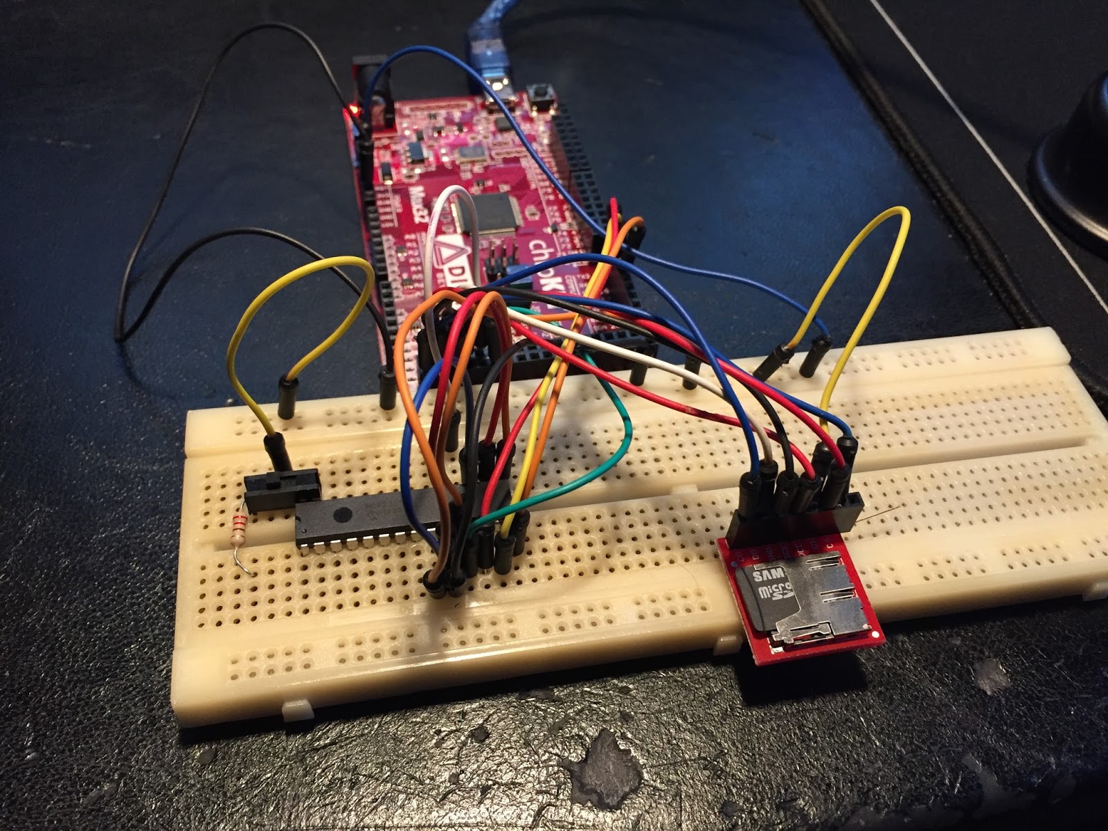
1) I/O expander MCP23S17 and micro SD in action. Super awesome toggle switch as input. 

2) Darlington transistor array ULN2308a driving TIP107 along with TIP102's.
Very nice combo, although not entirely logic level they are bipolar transistors
and react similarly to input. No "ramping up" here - and - no flickering at all! :)


I've also decided to give GI and flashers their own dedicated lines controlled by TIP102's and a MCP23S17. Flashers due to the voltage requirement to duty cycle them and GI for - worst comes to worst, a little flicker on a blinking light is no biggie, but flickering lights that shouldn't be, is.

I thought my old code was pretty optimized but take the old render routine, for instance. It performed a single row update in 100uS, and now I'm down to 50uS including updating all lights, all switches, all cabinet inputs and solenoids.... AND twice the amount of colors.
Overall, everything is high frequency SPI, direct port writes, updating other parts while one part is busy and maximizing use of hardware features and interrupts.

*pats himself on the back*

Friday, February 3, 2017

Status Machinima

Due to popular demand, here's a short update. ;)

I've more or less abandoned Fritzing.
For designing small circuits the program was fine, but the software became quite slow and unresponsive once the number of components increased. The program is nice, but needs maturing and it's officially not out of beta yet, so I'll hold no grudge. :)

I have since reached out to the good folks at Diptrace, who nicely enough supplied me with a non-profit license that allows me to build the board(s) I inteded. Very nice! I will most likely build a main board and a power board (I/O board, if you wish). That allows me to swap or update and avoid creating a totally new board in case of disasters...

On top of that, I've learned that the I/O pins on Chipkit Max32 are heavily shared, so I've needed to come up with some voodoo to make it all work out with the aid of I/O extenders. I've ordered a bunch of IC's to properly test this before designing the circuit based on the new circuits, including buffers, EEPROM, darlington transistor arrays and resistor networks. All fun and new components!

So, that's that for now...
Until next time - game on!