Monday, June 6, 2011

A little reconstruction here, a little reconstruction there...

... and we got sound!

Well, at least sound from one unit. The other one hasn't been ordered yet.

I had quite a struggle getting stuff to work and selecting the correct serial settings for the MP3 Trigger v2. The problem began with the first serial port occupied by one of the power boards connections. I.e trigger a sound - trigger the solenoid. Not good.

I tried resorting to using software serial communication instead...

...but after a long troubleshooting it turns out that the baud setting was not changeable in the ini file as I believed it would be. Since the baud is fixed at 9600 for software communication I couldn't use the SoftwareSerial library for Arduino to create a custom pin for serial communication. But it worked itself out alright in the end since the Mega2560 has three additional hardware serial ports that I could use instead. 


To get more than line-out level audio I had to get a small amplifier. I figure for testing purposes, a simple 7$ circuit would suffice, correct? Yes, it did. But I won't wake the neighbors with this! 


1) Cheap audio amplifier. This was gathered from a cheap MP3 speaker set that was mercilessly butchered and brought back to life by the ATX PSU. The next question is how I should mix the two sound boards' output into one stereo channel that can be sent to the speaker set...
I also spent a lot of time rewiring and cleaning up the electrics inside the cabinet. Now I got dedicated connections that I can tap +3.3V, +5V, +12V and +48V out of. Also, I rewired the Arduino and the one (later two) MP3 Trigger I got to use the computer PSU instead of a dedicated PSU for Arduino. 

2) Top: +48VDC connections, fusebox, +12VDC connections
The other top: Switchboard, temporary speakers
Center: +48VDC power boards, ground-bridge, Arduino, sound board, (cheap) audio amplifier
Bottom: +48VDC PSU, PC ATX PSU, +3.3/+5/+12V power connectors, extension cord


More power, cleaner cabling.  I like.

Saturday, June 4, 2011

Milestone 1

There's magic in the air tonight!

First, an incredible day in Malmö with my wonderful girlfriend (who deserves lots of credit for putting up with me building a pinball machine in the living room). We visited an exhibit there about vegan food and had a great meal. Highly recommended!

After that I wired up both flippers and kicked the ball around with the new power boards. Worked absolutely perfect! I accidentally put my knuckles in front of the flippers at one point, so I can guarantee they pack a heavy punch! I also tried the table at approx. 10 degrees angle and there were no problems at all hitting the higher places with force, so my initial design with quite high ramps should be alright.

Now that I know everything works as intended I can focus on getting the reset of the board and functions in place!

Wednesday, June 1, 2011

We're in control!

It turns out me burning the Wonderboard wasn't really my fault. I had a faulty coil so the circuit shorted. Instead of the minimum 4Ω my coil was 0.004Ω....

Ok... I lied. It was my fault also. I need to have normally closed EOS installed, mine was normally open. That also caused the high resistance coil never to trigger and thus burning the coil when I applied the +48VDC current.

This is how it's supposed to look when done (or redone) correctly:

1) The redone flipper assembly. Note the normally closed EOS switch. I've also installed the capacitors now. The nice thing about this setup (the correct way etc) is that if the EOS switch breaks, the resistance of the coil gets locked in high resistance, which means that the coil shouldn't burn out.
 
2) A closeup of the connectors. I've decided to use 'hot-plugs' so disconnecting the solenoids will be quick and easy if they need repairs. It also makes it impossible to connect power in the wrong direction since the cables will have matching pairs.

I've tested the setup with a regular ATX-powersupply and the new power driver boards and it works like a charm! Will be receiving my ATX-connectors in a day or two so I can supply the driver boards with +48VDC instead... (Wish me luck!)

Also, I got my MP3 trigger today, yeah!
Now I just need to connect a powersource (buy a powerplug 'head' or drive it directly from Arduino's +3.3VDC) and get FAT16 microSD flash card and I'll be playing MP3's like there's no tomorrow!


Can't wait! 

Tuesday, May 31, 2011

Changes in the hardware

I've been having a secret the last week...

I accidentally fried some components in the Wonderboard while testing it.
If it was due to the reversed polarity of the cabling and lack of protective diodes or simply to weak cables to run the current needed should be left unsaid.

It also turned out the MOSFET got so hot simply because they were not saturated fully fast enough since the Arduino "only" has +5VDC@0.04A. The specs are around +10-20VDC@0.08A to trigger it, I learned after reading the spec sheet a little more carefully. This created a slow accelerating "puuuuuull" instead of an instant "PULL!". Doh...

Anywho -
I decided against repairing the board and ordered myself a couple of power driver kit's and a relay board from Sparkfun along with a MP3 board so I can get started with the sounds. These are professionally designed and all I need to do is to solder 'em up.

The soldering of the power boards went quick and well and they seem to function properly. Hopefully they'll handle the current needed. This kind of put me at a crossroad, should I -

A) Use relays to drive the flipper coils with the buttons directly and the power boards for the rest.

The obvious benefit would be to keep the high power flipper coils separated from the relatively small circuit paths of the power boards.

The drawback would the staggering 15ms time it takes to trigger...
Also I need to get more relays.


B) Use the power driver boards for all solenoids (but probably only one high power coil per board), and the relay to enable/disable current to the boards.


The benefit would be cleaner cabling and faster triggering of the solenoids, which is crucial for the flippers.

The drawbacks are the relays themselves - I don't know if they can handle up to +48VDC@7.6A...


The main reason for my doubts are the lack of details around +48VDC usage. The specs only show an example for +28VDC@20A... I do know they work with +48 VDC (I had to test it...Curious George ) but I don't know how much current they can handle at that kind of voltage and for how long. I did test it briefly by triggering the slingshot solenoids and it worked as a charm!

As for the MP3 board...
...Sadly Sparkfun had a stock error on their site so it turned out they had to backorder it. But it's shipped now but has not yet arrived. Will let you know how it performs as soon as I get it!

Monday, May 23, 2011

Bumpers and Flippers

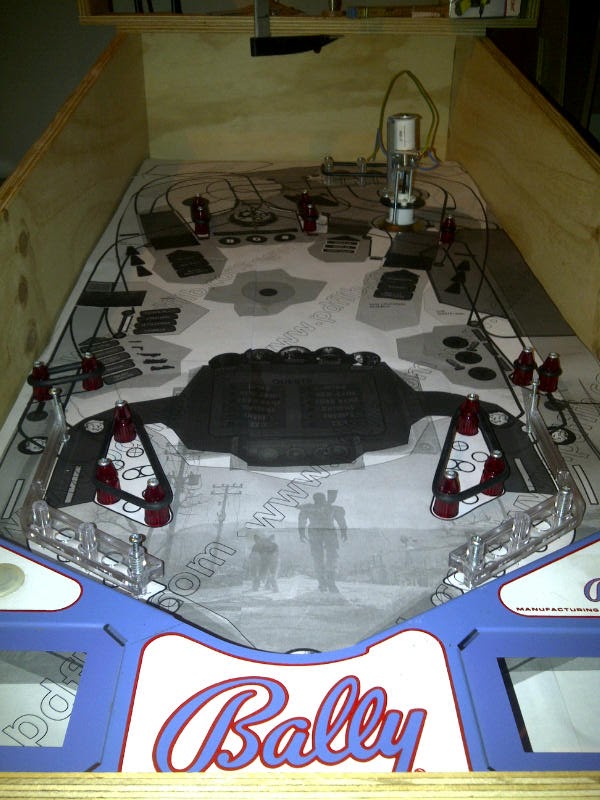
Yesterday I installed the slingshot-, bumper- and flipper solenoids. Not currently wired up, but at least they're installed now! Nevermind the sloppy woodwork, this is basically a dummy board to get the alignments correct and to testdrive the design. I expect to do at least one revision before the board will be finalized.

I'm currently planning for light installation and the routing of the cables, but since this is a prototype board I won't install any lighting yet.

Here's a couple of pictures for the craving:
1) Slingshot, nevermind the woodwork....


2) Pop/Jet bumpers. They were tricky to install!


3) Flippers! 

Monday, May 16, 2011

Theme's selected!

I've begun the graphical design now, based on a theme that I hold very dearly. It will be absolutely awesome and as the idea came to my mind it became totally obvious that this was going to be IT.
Unfortunately I cannot tell you any details until I've come further in the design, don't want anyone to beat me to the punch!


Some of you might recognize the graphics, but you'd probably need to be hardcore for that at this stage...


Hopefully the copyright holders will forgive me for doing a mild boundry-breach, but I'll make sure to give them proper credits!

Thursday, May 5, 2011

Switches, Solenoids and Light Emitting Diodes

Yesterday I finished the switch-board that I'm almost completely satisfied with.

The only downside is the connection type for the switches that I've chosen, a simple 'plug & play' solution would be nice but the current version has screws that hold each cable. Not the biggest concern, since I can easily put better connectors onto the cables themselves.

I've put diagnostics LED's on each connection so that I can clearly see when a switch triggers. Should come in handy during the playfield and ruleset testing! All in all, the switchboard has 32 inputs - not sure if that will be enough for the final version, but it should take me a long way. Although not shown in the picture, the dark side of using experiment boards is evident, since each input had to get the ground, power and control connections wired. It's a mess, really. There's around 352 solder points in this design... I'm really happy I bought that soldering station!


I've also attached diagnostics LED's to the solenoid board as well. It immediately showed that "Solenoid 5" was active all the time. After a little troubleshooting I realized that Arduino's serial2 used the same pin so I had to disable it.

I've also put little rubber feet on all boards so that they are elevated a bit from the surface and also get a little more protected from vibrations and shocks. The ribbon/flat cable design I've chosen showed to be extremely nice when debugging, as the board constantly moves from the cabinet to the workbench! I'll probably do this on the solenoid board as well in the future.