Wednesday, December 28, 2016

Big D vs Big S

Hi ya'll. 

Been moving my programming environment from Windows XP and an old laptop to OS X and a modern computer, and that sh#t turned out to be a lot more difficult than I anticipated. Moving from MPIDE 0023 to Arduino 1.6.13 sure didn't help either and even basic serial communication and switches stopped working...
Anyhow - after a hefty troubleshooting session that lasted a week or two; I'm back in business.

And despite some issues, I can now work a lot more easily on the programming for both boards and the newer computer allows for more optimized compiling and thus faster code. This means the display and servos run more smoothly.

So during the coming months I'll get started in the code refactoring and game mode creation. But for now; here's a short snippet of Mr B in action. (very much beta, obviously). :) 


Oh, almost forgot -
I've got myself a Big Sister that stands nicely next to the "evil" little sister and the vent, just above the "SISTERS FOREVER" mode light. She will probably not be animated or lit, but a LED-eye would probably be possible in the future... 

1) Big Sister. Had her on the cover, would be rather weird not to have her on the playfield as well. I have temporarily fixed her to the VUK-habitrail without the backpack, but I'm thinking about making the backpack "wrap around" the habitrail, making the ball go through it. That would probably mean I have to break the toy though, which I refrain somewhat from... 


Monday, December 12, 2016

Are we there yet?

Not quite, but at least the machine is done enough to be moved into the living room. :)

1) Close, but no cigar. But at least the scotch is cooling, awaiting the cigar!

Thursday, December 1, 2016

Double polarity LED's... who knew?

Oh boi. I'll just say it.
Shame on me - I missed a couple of diodes.

The bumpers and flashers were still "unprotected" and on top of that, the LED's I had installed were double polarity meaning they worked in both directions....  Who could have known, right?

The good news are that lights are now working somewhat properly (we'll get to that) and I've updated the main board with the correct lights and what not. This means I'm kinda back where I was before recreating the light board. And that's a good thing! I've also fixed sound and music, which had a few bugs that has stayed uncorrected since moving to the new system and board. Tried a couple of quick games too. 8-)


The bad news is that there is a slight flickering when a couple of lights are active at the same time. This flickering occurs on the light board itself as well, so it may be due to lack of power in the board or shift registers. I'm currently using a row/col based approach, which lights up to 12 lights per channel. I will try converting to col/row so that each row only ever power a single light at once. Hopefully that solves things.
 
I've also noticed that the servo handling the target bank was dead.
So I replaced it, only to find out that that servo too died after a few on/off's. The servos are beefy ones and are moving up to 5kgs, which is more than enough for the purpose, but somehow they die anyway. This last one has frozen in place, unable to turn, but it sounds like it's working. I'll have to investigate this further.

On top of that, the captive ball lane captures balls despite having no ball lock. The irony...

Code revision on the game will have to wait until the servo is corrected, as well as the captive lane.

But yeah, progress! \m/  

Sunday, October 30, 2016

It's not me, it's.... something else.

So, got my dirty hands on the light board and re-did the whole "extra board" thing. It still looks like crap, but at least now it doesn't glitch or have connectors that risk failing.

Then I realized, by accident really, that there was no ghosting to speak of in the board.
There wasn't even a problem with the board itself, besides the glitchy MOSFET, that is.
The problem is that somehow, don't ask me how, current is traveling back through the light grid/matrix and "triggers" other ports.
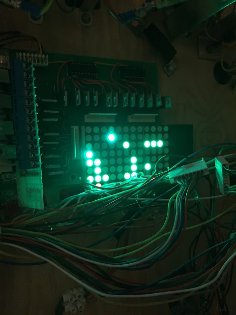
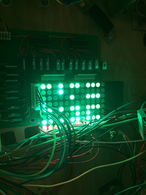
1) Light board only. No light cables or playfield connected. The camera had a rough time trying to photograph this, but everything looks just fine IRL. Crisp and sharp lighting and most importantly - no ghosting.

2) The very same light setup except that the power connector to the playfield has been connected as well. Behold - The mother of all double triggering, ghosting, annoying and downright irritating setup is created.
I don't know for sure at this point why this is happening, and it's rather hard to measure with a multimeter. Since it's using 3 MOSFET's enabled per active light it's also extremely/"impossible" to troubleshoot outside the cabinet. But here's what I got so far -

Everything is working perfectly with no extra cables attached.
Since the board has diodes from each MOSFET to the power lines and that the LED matrix on the lightboard is just that - LED's - current must be coming back through the very same power lines.
Unless I'm measuring wrongly, I'm also reading negative voltages on the ports that should be off.

That means the board _should_ work perfectly fine and that the problem should indeed be in the light matrix/series on the playfield itself.

Could I have connected something wrongfully? Possibly.
But still, I don't understand why it should be that - I got diodes installed on each lamp. So current can only flow in one direction, unless I made a mistake somewhere. But with everything attached there's just too many variables to investigate. Have to narrow down the search area...
I'll most likely troubleshoot this in a rather naive way -
By disconnecting all power cables from the playfield and adding them back one at a time (possibly with a diode as well).


Wednesday, October 5, 2016

Light and Sweet!

Finally got a little work done!

Not a whole lot, but at least lights are active again. :)
The ghosting is pretty horrible thou, but should be easier to troubleshoot this now since I have a proper load on the circuit.

 1) Long time since the board was lit up!
Looking forward to the day (hopefully soon) when I start re-labeling the lights and hopefully get rid of the ghosting. 

Thursday, August 4, 2016

The Bride of Frankenboard

Rise, my child, RISE!

1) Bride of Frankenboard. I wanted the add-on board (to the left, with the blue sockets) to be somewhat serviceable so I created it to be removable. Originally I had a fantastic Arduino-shield like design with headers that the board would slot into, but there just wasn't space. At the moment this is the best option, but a later revision will be larger in design so that it's in fact serviceable and not just in theory (i.e without a ton of cables in the way).

Alright -
So I've created a daughter board to the light board made from an old obsolete switchboard, hence the bulky blue sockets, containing all N-Channel MOSFET's to allow for logic 5V switching of loads independent from the logic (i.e > 5V). Link to circuit.

Seems to be working fine so far!

The downside is that it's hideous. And slightly erratic in its dependency, as it seems to have a glitch somewhere, but I can't see or find it. So I guess this board will have to be a sort of "proof of concept".

But it does work.
And that means I can continue with other stuff.


2) Ignoring the broken magnet holder, here's an active light with 12V (i.e around 1.5V due to duty cycle).
Still not super bright, but...

3) ...good enough for the purpose. I will try higher voltages, probably 24-36V, in the future
as well as bulbs won't light up properly otherwise. Either that or actually converting to LED's... 
Also, note the washed out colors of the text. I have a solution for that as well, but that's a later issue.


Thursday, July 21, 2016

Let's introduce our little friend; Little Mr Duty Cycle

Forgot all about the LED's being duty cycled while being multiplexed.

8 rows active (~12.5% duty cycle):
1) 12.5% duty cycle, quite dim, but still alright with LED's. Incandescent bulbs barely light up.


1 row active (100% duty cycle):
2) 100% duty cycle. Everything works peachy, including incandescent bulbs.

When all rows are active the voltage is roughly 1.2V, thanks to the ghosting - otherwise it would be lower. This is with 5V input. To get it as bright as it should be I think I'd need to go up to 30-48V for 5V actually, which requires separating the logic chain voltage from the drive voltage. 

And even weirder - the LED doesn't light up much at all when using the 12V line, so it looks like something is wrong there (probably programmatically, as that row requires special handling etc).

Welcome to nightmareland. :/

Wednesday, July 20, 2016

Now what?

Ok, so I went ahead and soldered separate data, clock, latch and enable lines for rows and columns and updated the code to reflect the changes.

STILL ghosting.

Albeit less, it's still apparent when the surrounding is dark. 

There's no ghosting when not switching rows so at least that narrows it down slightly.
I'm thinking that either the LED modules suck, or the MOSFET's doesn't close fast enough. The MOSFET's are rated for logic voltages and should fully saturate. However - Considering the data sheet the opening and closing times are rather large thou:

Turn on rise time: 210-430 ns 
Turn off fall time: 110-230 ns

This leads me to believe that (I haven't calculated this yet) perhaps the switching is a bit on the slow side for a LED matrix purpose.

But it is what it is, and quite possibly this is not an issue when connecting the actual lights.
So I'm moving on for now.


Edit:

So I lied.
I haven't moved on.

Apparently I need to apply some kind of load that removes excess current still in the circuit/LED's after the MOSFET's themselves have closed. It makes sense, as explained by Chris (dcel):

"With no load after the voltage falls below the LEDs turn off voltage, there is nothing to bleed off that stored energy, hence that "afterglow". You may want to put a pull up resistor on your n-chan drain as well so its not floating.

     In my troubleshooting, I put an incandescent lamp in parallel with the LED lamp and that made the channel turn off hard. Uhm... interesting, threw a 100R in with same hard off result. I experimented with increasing resistances and found for my app, that 100K was sufficient to turn the FET off hard at 1ms or less. Good enough for me. "


Something like this.

1) Fancy schematics. The resistors around the LED should lead current away from the circuit when either side shuts off.
Sounds fair enough and relatively easy to test without destroying something. #FamousLastWords

There's also ways to push the fall time below normal by forcing it shut with negative voltages. But that sounds at lot more complicated and risky to me. On a plus side; I've also found evidence that Williams had problems with ghosting in hardware as well and worked around it in software.

Tuesday, July 19, 2016

Resolution of the problem!

Success!
The board is now running different voltages without any interference!

I swapped the P-Channel for a N-Channel on the 12V "rail" and pull-downs to pull-up's on the remaining P-Channel MOSFET's. No more weird double triggering.

As for ghosting;
There's unfortunately still plenty of it.

I'm thinking this is my fault when designing the board since rows and columns are operated on the same chain of shift registers. This means I cannot turn off rows and columns independently from each other but instead have to rearrange everything at once. I've also hardwired the OE (output enable) of the shift registers to permanently being on, which of course is a part of the problem.I don't expect this to be a big issue, but I'll have to see.

In case it is a major nuisance I can always add a few control lines and possibly OE as well.
I'm thinking OE would be most significant, as this would allow me to properly turn off the matrix while transitioning rows (and columns). 

Monday, July 18, 2016

Confirmation of the problem

Indeed it's the voltage that is the culprit, and there's a solution in sight.

I've created three example circuits;

Top - current and erroneous 12V circuit (should be off)
Middle - current and functional 5V circuit (is off)
Bottom - proposed and functional 12V N-channel circuit. (is on)

Example circuits

( No resistors in these circuits, but they don't affect the outcome here )

Ironically - a while back when transferring the lightboard from design to product, I found that I couldn't use N-Channel MOSFET's, and yet here it is saving me. I must have made some real booboo's on that breadboard when I deemed N-Channels nonfunctional for the lights, since there's really no reason for it not to work - it's all about which direction the current goes.

Weird Science

Ok, so I've found the problem with the lightboard after extensive search - When using two different power voltages (sources?) it doesn't work.

Why?
I honestly don't know.

I've double checked the hardware and rewritten the software, nothing seems to make a difference. I've done no change in the circuit, but simply removing the +12V and attaching a cable from the +5V input to the +12V makes it work perfectly. The both grounds are tied together as well and has always been. So the circuit itself should be alright, I guess?

My best guess now is that somehow power leaks into the "on-switch" of the 12V MOSFET since it's not connected to the same power chain as the rest normally, and therefor possibly allows the current to flow differently there. Putting diodes could possibly remedy it. But there's really no room on the board for extra parts, meaning some ugly Frankensteining of parts on top of parts etc.

I'll keep looking. Nobody wants weak 5V flashers... :C

Edit - 

Ok, I think I'm on to something here. And if so, it's a hardware error by design (by me). 
I'm connecting the gate to ground to keep it from floating, but that is how it's done for N-Channel MOSFET's, not P-Channel as those are active when grounded/low. So that'll have to change and will probably help a little with the ever so slight ghosting issue. 

Secondly; 
I thought the VGS value of a MOSFET was some kind of fixed requirement for turning it on. Well, it is - but it also depends on the load. So in this case when using logic level voltages (i.e up to 5V) the gate can be properly held shut by the shift register as the voltage is less or exactly the same as the gate voltage. In comes 12V and I'm suddenly short 7V to properly close the gate using my 5V, and the circuit is held open. Imagine closing a door standing in a river compared to closing a door in a shower, the pressure of the river is just to big to properly close the door and water will leak through etc. 

So I need to first fix the resistors from pull-down to pull-up, and then I guess add a N-Channel MOSFET on top of the P-Channel to act as a valve for opening/closing the P-Channel and thus the heavier load. I'm so glad I've moved the board to an easier to reach location!


1) Colors are off and the light numbers doesn't correspond with the correct channels yet, but you can clearly see there's no wrongful "double" triggering here.

Saturday, July 16, 2016

Balls Be Lockin'!

Well, soon enough at least!

This is what I've come up with so far.
Should be fairly easy to manufacture; Five sheets of 10 mm plywood/board with standard drilling/sawing at most and a couple of 2 mm aluminum details etc.

1) Left: Open state. The holder solenoid bracket is spring loaded against the main solenoid plunger, and once the main solenoid triggers and the plunger reaches the endpoint, the bracket pushes forward and locks it in place. Right: Closed state. The holder solenoid and main solenoid is inactive and springs are doing their thing together with physics. When it's time to open I'll fire the main solenoid briefly to release tension, hold the holder solenoid while the plunger drops and then release the holder solenoid.
There are a few eyeballers here, but overall it should be pretty correct. The "fork" itself is based on a couple of bolts I have (with the screw part sawed off in the design) and they are a little shorter than I would like them to be. I will also have to double check that the ball won't squeeze through the gap. In case it does, I'll have to drill new or bigger holes in the playfield since the captive ball posts where 2-3 times larger than these bolts.

Should shit hit the fan, I got a couple of blue steel ramp flaps that can be placed on the playfield "floor" to cover up any unwanted holes. But I really hope it doesn't come to that! :)

Wednesday, July 13, 2016

This One's For You!

Woohoo, an update! ;D

Finished all diodes (I think) today, and got plenty of work done on the machine. For starters I moved the entire light board to the playfield for easier access and debugging/status checking. Unfortunately I realized that there appears to be some kind of error with the 12V line, as these are always active when one of the 5V LED's in the same column is active. I believe this to be a software issue as I cannot reproduce the error by powering rows/cols manually. Had there been any kind of short circuit that would have shown, I think.

The downside is that my programming environment is a very old laptop and for some reason I cannot compile code for Arduino anymore, so I'll have to use my desktop computer. It's quite cumbersome to setup so I'll put that to side for now.

Edit:
Actually, the row-MOSFET's are active when held low, so it's not entire impossible for the 12V MOSFET to be wrongfully and constantly grounded and therefor constantly active. In the schematics all rows circuits are the same and only the voltage differs. But maybe I connected something to ground "just in case" and since I've previously only connected the 5V line while testing the board, the problem could have been there from the start. I will investigate this.

Edit 2: 

Nope, that's not it. The board follows the schematic (who knew?!) and they're all connected identically. I cannot measure any differences between the functional rows and the erroneous either, so it's gotta be something in the code. Probably a clock pulse in the wrong place or something like that. Let's dive into manuals, yeay!  


1) Cluttered cable mess and the installed lightboard. The board sits on rubber pads and has extra support on the edges to prevent it from falling down, should it ever vibrate loose (not visible here).

2) Dimmed global lighting and example lightshow running. Note the erroneous red row that aligns with the green lights. No actual light has been plugged in at the moment since I need to work out the issue with the programming/board before applying real voltage across the playfield, but even then it's just 20 cables that needs to be soldered. Not a big deal at all.

Then I finished the one-way gate with double switching, meaning that it blocks shots from the front but registers hits, while letting balls from the bumper area pass through and still register hits. This allows for a greater range of options for game rules etc. I'm quite happy with how it turned out, even if the final form of the switchblade had to be reshaped ad-hoc since the nut was placed differently than in my "test rig".

3) More or less the player angle of the switch area. It's got a bit "last minute" to it, but hopefully it'll play alright and the benefits are far greater than the possible visual aspect of it. But honestly, I think the Quadtych deserves to be a visible part on the playfield - and now it is.
4) Birds view of the switch area. The metal rail in the bottom (i.e playfield right) was bent with a nice fit. The original part was just too short and I was tempted to put a pole between the bumper and the rail, but then I found a slightly longer rail in my "box of random parts" which worked perfectly. Guess I've been racking up some karma points at least... :) 

5) Switch close-up. Took a bit of fiddling to get right, but it works great. Hope it keeps running smoothly in the future too.

 Lastly, I've begun work with the ball-lock / up-post thingy.
At the moment all I've done is removing the old captive ball and modifying the plastic overlay slightly to better show the locked ball.

Next I plan to construct the actual ball lock device itself, where the problem today is two fold;
Firstly there's the issue of attaching the holder solenoid to the main solenoid. I need to find a good material that I can process without heavy machinery. I'm thinking a thin(isch) sheet of aluminum should work. Plan B is to construct a plastic placeholder while I think of something else. I'm refraining quite severely from purchasing new parts at this stage, but if I have to; well, I have to.

Secondly, the "fork" I was planning to use to hold the ball was of a wood screw type and is unfit for mechanical use, so I'll have to find an alternative for that. I don't think I can use an official Stern (or similar) ball lock as the space is very limited where I'm installing it. At least in the blueprints I've looked at it looks too big.

Well, that's all for now. Hopefully I'll have functioning lights and a ball lock next time! :) 


Tuesday, June 28, 2016

Shame! Shame! Shame!

My plan failed - I have not been able to work on the pin as much as I wanted to.
Music, life, family and a lot of other cool things has simply been taking all my time.
But fear not; Soon the new workflow shall rise from the ashes of the old! ;)

Also; Game of Thrones.
Last two episodes were killer! \m/

Sunday, May 8, 2016

Vacation's up!

So, back from my mini-vacation!
Been doing nothing but enjoying the weather, visual pinball 10 and life in general. #thumbsup

Starting this Monday I'll begin working on the machine on a schedule.
Figure it's time to get it up and running, right? :) 

Wednesday, March 23, 2016

Die...odes.

Progress is going slow, not only did I solder the ground cables wrong. I also soldered a lot of diodes in the wrong direction. I soldered the first one wrong and used that for reference for the next etc...
But on the plus side; I'm halfway done with the soldering of diodes now!

The gate and ball lock is taking shape as well, need to rearrange a ball guide and drill a few holes but other than that it shouldn't be much more work.


Sadly, I'm starting to toy with the idea of a kickback in the left lane too, haha. But I guess that'll have to wait. :)

Monday, March 14, 2016

Through The Gates of Hell

Here's a quick preview on the test version of the one-way gate.
It's not nearly as slimmed as I would have hoped, but without special wire bending tools it's impossible to bend smaller angles. The wire is tough!

1) Partially assembled gate.
The gate has changed since this photo was taken, will post update soon.
2) Position on the playfield. The switch registers hits from front and back but
will only allow balls to pass through from the bumper area.

Thursday, March 10, 2016

Nothing bad...

...that doesn't bring any good, right?

Having some forced time-out from soldering made me focus on game rules instead, and it hit me -
I'm not done with the playfield just yet.

I have a one way gate planned, which actually was planned for but never made it to the "final" playfield because of time and technicalities. The gate would be sitting between the vent and motorized targetbank, preventing direct shots (or at least partially) into the bumper area. I might do a half gate to allowing less-than-direct shots to pass/bounce into the bumpers thou. I did work around the lack of a gate by blatantly pushing The Masterpiece and New Years Eve-corresponding actions up one floor, to the upper level. But this way allows me to use my original ideas which, quite frankly, sound a lot more fun!

I also found a spare flasher that I can place somewhere now that I got plenty of free flasher-channels. I'm thinking it would be a cool effect to put it behind the Big Daddy and possibly killing all lights and strobe that flasher during his awakening. The shadows should be pretty cool and the effect of the red eyes in the dark would be nice too!

The next part is getting rid of the captive ball and replacing it with a ball lock, similar to the one i recent Stern games such as Avatar, Rolling Stones or X-Men. It will be a tight fit, but I have all the parts and just need to Frankenstein them together. The best of it all - it costs me more or less nothing, and is more or less a matter of screwing things together.

This should be the equivalent of taking a bathroom break on a road trip, so nothing major. While waiting for my soldering iron replacement to arrive, there's not much else I can do. :)


Friday, March 4, 2016

They call him jinxed.

I was just about to start soldering on all the diodes and....
My soldering iron decided to die on me.

At this point of "two steps forward, one step back" I just got to ask myself - How badly jinxed am I?
Seriously, does that even happen to people?

A replacement soldering iron has been ordered so now I'm waiting for that to arrive. :(

1) Fresh diodes! Get your diodes here. 

What 3 GB graphics get you...


I can't remember if I've posted the full table graphics overview yet, but thought I'd do that. :)


Tuesday, March 1, 2016

Research!

As a friend told me - I really should have done a little research before soldering away...

Anyhow;
The problem is easily and cheaply fixable.
And it will be fixed properly and according to how pinball machines are supposed to operate.This picture blatantly stolen from Marco Pinball pretty much explains everything needed to know.

1) Lamp socket with diode attached. I'm frankly a bit ashamed I didn't research the purpose of the extra lug when I checked the connections....


What I did was soldering my ground cables directly to the outer pin, efficiently bypassing the design of the lamp holder. In other words, I did exactly what this image told me not to.

2) The problem explained in detail. On my machine the row and columns are "swapped",
meaning power is coming from the rows and columns are ground. 


The solution is pretty easy to put in place, so now I'm off to shop for a bunch of 1N4004 diodes - which, luckily, are very cheap compared to the the cost of converting to all-LED... 

Saturday, February 27, 2016

We meet again, Captain Setback!

I was having a great time soldering new light cables and everything went smoothly... I thought.

1) I was happy. Until I tested the circuits...


Introducing, in the red corner - The Problem.


2) A typical layout with two power lines and two ground lines.

In the picture above, connecting Power 1 and Ground 1 should light up Lamp 1. The problem is that since I don't use LED's, which are single direction only, but lamps/bulbs in most locations, powering that line will also light up Lamp 2, 4 and 3 (in that order). Basically it's a grid of interconnected lines so "everything" lights up simultaneously. Doh.

...and in the blue corner - The Solution(s).

I planned the matrix layout based on LED's, so the easiest solution would be to simply replace all bulbs with LED's instead. That is rather expensive however and I really want to keep it "lamp-agnostic" in order to use whatever lamp suits the most.

Another possible solution would be to use current restricting diodes on each ground and power line. Slightly less expensive and should be quite easy.

The third - and here's where my hope lies - possibly solution: Using the light board's built in current restricting diodes on each ground and power line. However I'm not fluent enough in electrics to know if a single diode at the end / start of each line would be enough to keep current going in the right direction all over the playfield. I only know this once everything is hooked up, and I have roughly half of the ground cables left to solder, and in case I need to adjust something I'd rather do it now than retrace my steps later.


The million dollar question: 
Is it enough to "correct" the current direction at the start and end of each line, even if the cables are not drawn in series, but rather branch out every now and then? Would the, say, blue chain above benefit from a diode between Lamp 2 and Ground 2? Would the diode stop that from happening since that line is still connected to the diode?

Or would the current pass on from Lamp 2 to Lamp 4 regardless?

Edit:
I've found a great tool online to troubleshoot circuits. Using this (which I assume is rather correct) I can see that it won't work with a single diode. The current would still pass in the other "legs".
I will see what the best solution would be, but right now I must say changing to all LED's would be preferable... :/

Check for yourselves here:
Lamp/Bulb based:  http://tinyurl.com/jk38dwm
LED based: http://tinyurl.com/gvbssy2


Friday, February 26, 2016

I'm not alone!

It turns out I'm not alone in this world building a custom pinball machine!

*insert shocked audience reaction here*

Not that I ever believed that, but now it's easier than ever to keep track on the projects that are out there. With Pinball Makers website and all the great custom games that are currently in progress. :)
Head on over and see what the fuzz is about: http://pinballmakers.com/wiki/index.php/Custom_Games

I specifically like this Nightmare Before Christmas table by Mark Incitti.
Looks really solid and seems like a very fun table - and you can play it today using Future Pinball!


Btw, this is totally not an ad.Even thou it sounds like it. ;)

Btw 2 -
I'm considering rewriting all game rules from scratch.... :O 

Tuesday, February 23, 2016

Love shine a light....


Almost done with all power/row connections now. :) 
It looks like crap, but works - and that's most important right now!

I found out that I'm short eight light ports, so I had to combine a couple of GI ports (again) in order to have enough for all the important lights. Silly me to forget that 8 of the ports on the flasher-row wouldn't be usable for the other lights...Thumbs up on that one.

The lights are grouped in big colored chunks, making it quite easy to visually debug or trouble shoot faulty cables. This combined with the maintenance mode and on-board LED visualizer will make light problems a breeze to handle in the future. 

It's nice to have a little progress at last! 


1) Cables that only a father could love...

Saturday, January 23, 2016

Stuck in the wasteland...

Long time no update, sorry about that.

I've been, as some of you have guessed, completely sucked into the world of Fallout 4. Pretty nice game and much better than Fallout 3 in my opinion. (However, dragging way behind Fallout 1 and 2...). Playing the game on a projector and gamepad gives the wasteland it's proper dimensions. #nice

Other than that -
I'm at this stage of building were it's really tough to keep going and feel that unless I got a full day to spend on the machine, I don't bother at all. Will try to change my attitude regarding this so that "a cable a day keeps the doctor away". It's taken me much longer than expected since I'm kind of a perfectionist when it comes to details. I'm never really happy a long time with the results which is why I tend to remake stuff all the time. :)


But it's getting closer to completion and once all new light cables are in place the "Version 1.0" coding will commence.

Thanks for your support!
It means a lot and takes me through the rough patches! :)