Sunday, February 26, 2017

Order's placed!

Fingers crossed - board is ordered!

But not from DirtyPCB's - from Seeed Studio instead. Half the cost as well, which is nice.
Minimum order was 5 so I'll have to spare in case I mess up!

Something like this will be what I'm getting:

1) Should be rounded corners, but the preview doesn't show. Either this manufacturer doesn't allow it
or the preview doesn't show them. Probably the latter since it allows for quick re-theming of the colors,
leading me to think it's simply a color rectangle slabbed on top. 
I also created and added a small PCB-adapter to push all random left-over pins into a single connector along with 5V, GND, serial and I2C for possible future add-ons. 

Wish me luck!

Monday, February 20, 2017

Putting Boards In Perspective...

Ok, so maybe I've gone a bit "home blind" here.
Just measured the board extremely scientifically by holding up a Max32 in front of the screen.

Turns out the board is a lot more compact than I thought when designing it.  :|

1) It's all in the details. In the fine, fine details.

Soldering this... should be interesting!

Saturday, February 18, 2017

Easy Peasebee.


This one feels pretty much "there", actually.
Just some minor tweaks and a good walkthrough of all pins and connections (and a final testing of each circuit again) - then I'll be ready for ordering!

1) My first PCB ever manufactured! Or designed, rather. Measuring in at 26x15 cm it's more or less the size of two experiment PCB's. Only this time everything fits on one card. 

2) Flip side. Since I'm not perfect I've designed all Chipkit pins to be accessible while it's attached. I've also added a
couple of "experiment" areas for IC's and additional things I may have forgotten or in case I add, stuff breaks etc.
The pads on the ATX connectors that are slightly smaller are unconnected, but I'll solder 'em on for support.

I think it turned out rather nicely actually. Pretty proud if I may say so. Let's just hope it works! ;)
Also... routing by hand beats automatic routing in aesthetics every day!

Thursday, February 16, 2017

Pesebee Rev A!

I've tried and tested all (I think) variations of the planned circuits, and they seem to work perfectly. So I've gone and started with the PCB layout.

1) Simple "everything at once" picture. This is 100% autorouted, so it's not the most aesthetically pleasing routing,
and I'll probably try to route at least the output elements before letting the autorouter fill in the gaps.
I think that the 48V traces needs to be bigger as well, at the moment they're 2.54mm wide.  

2) Since all my sub-boards (Chipkit, SD card, WAV Trigger) are red - and it's a nice color - I'll most likely go with red.
This is taken from another stage in development, so it doesn't match up with the drawing above.

I'm not entirely satisfied with this, and I missed a few items.  It's 23x14 cm large at the moment and probably needs to grow a little to accommodate the larger 48V traces.

So there's probably a few more revisions until I send it to DirtyPCB's for manufacturing. The Diptrace license I got was 500 pins, so it doesn't give me a whole lot of wiggle room - but I'm not complaining; Diptrace is an excellent software and pretty user friendly! :)

Monday, February 13, 2017

Revision Revised

I was wrong about the voltage in the last post.

Turns out I had connected rows and columns wrong (swapped really), so the lights were always on and stuck on the very first row. Doh... 

After a night of frantic coding, I've managed to do something really weird.
With an input voltage of 12V, I get; 12V out. Despite duty cycling at 1:8.
What.

I measured the voltage without anything connected, between P-channel output to N-channel input, it's rock solid at 12V when active. If I put a light there and measure the same way, it's around 1V since the bulb is stealing the rest of the voltage. The light turns on and off as I rotate the active light in software, so it's not constant on either. I am using pull-ups for the P-Channel MOSFET's, but it does feels a bit too good to be true.  :)


1) Chipkit driven by 12V wall wart, 12V out to P-channel TIP107's via the Vin-pin. The meter says 12V, but my senses says it couldn't really be. But it's bright enough to shine through a very dark smoked glass candle thingy.


Sunday, February 12, 2017

Square One?

Feels a bit like I'm back to square one doing these kind of things again... ;)
Only this time I actually know what I'm doing. Which sure is a plus!

I'm especially proud over the new code and setup.
The lights update at a very high refresh rate and gives a solid 3.01V when fed with 5V (duty cycled 1:8) and 5.04 at 9V. Presumably I'll get roughly steady 6V out of 12V too, which is perfect. Light rows and columns are all part of the same PIC32 port, thus the cost of updating all lights is the same as updating a single pin.

1) I/O expander MCP23S17 and micro SD in action. Super awesome toggle switch as input. 

2) Darlington transistor array ULN2308a driving TIP107 along with TIP102's.
Very nice combo, although not entirely logic level they are bipolar transistors
and react similarly to input. No "ramping up" here - and - no flickering at all! :)


I've also decided to give GI and flashers their own dedicated lines controlled by TIP102's and a MCP23S17. Flashers due to the voltage requirement to duty cycle them and GI for - worst comes to worst, a little flicker on a blinking light is no biggie, but flickering lights that shouldn't be, is.

I thought my old code was pretty optimized but take the old render routine, for instance. It performed a single row update in 100uS, and now I'm down to 50uS including updating all lights, all switches, all cabinet inputs and solenoids.... AND twice the amount of colors.
Overall, everything is high frequency SPI, direct port writes, updating other parts while one part is busy and maximizing use of hardware features and interrupts.

*pats himself on the back*

Friday, February 10, 2017

All Things Start Small

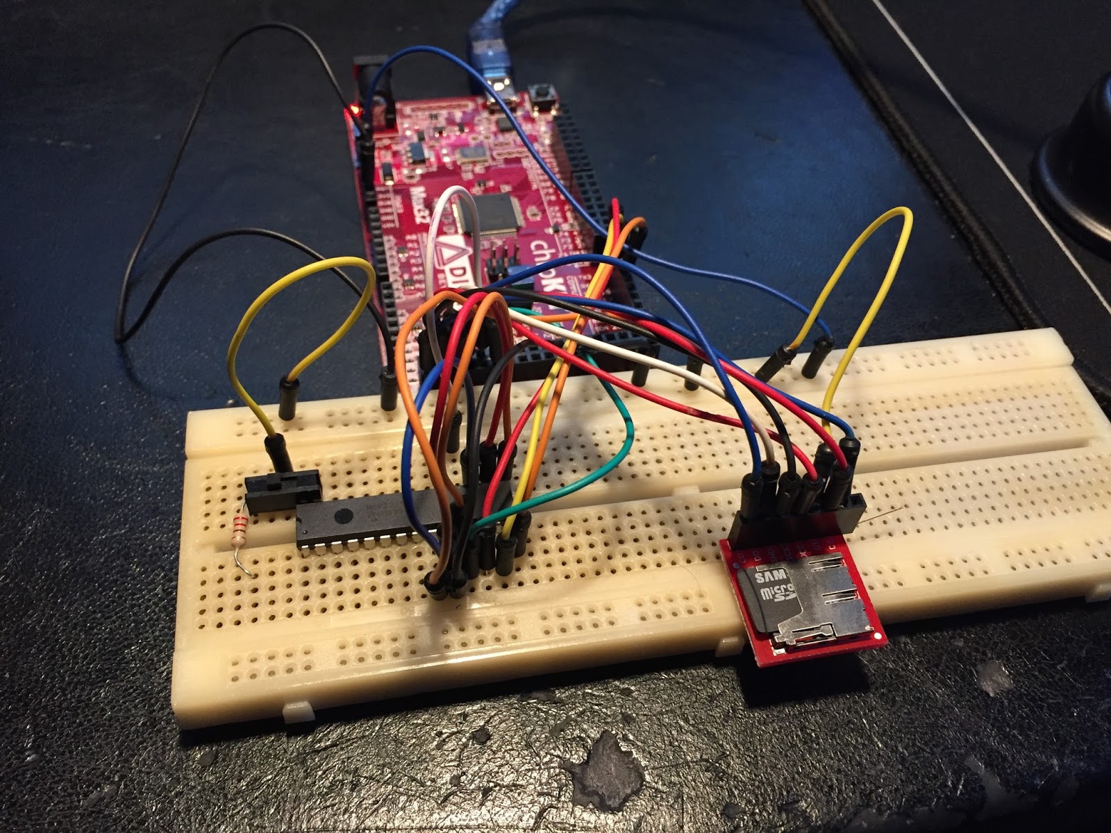
For the past days, I've been able to test most of my planned circuit board on a breadboard, along with some very basic rewrites of the libraries.

I'm happy to say that I've encountered no problems with the design or code so far, which is in no small part thanks to Majenko on the Chipkit forums for supplying a very readable overview of the I/O pins of the Max32. Of course, this information was available in the datasheet, but he simply presented it in a way the Digilent people really should have done from the start. Super awesome and did indeed explain why I had some trouble in the past! 

1) Image courtesy of Majenko, hopefully it's alright to post it here. Red/orange buttons with white labels are non-exclusive pins and will conflict with the others if used. Green are alternate names and purple ones are unique. Interrupts, SPI and I2C are shown as well.  

As for code, I've designed both DMD and SD reading to run via interrupts, meaning that while the DMD is receiving data or the SD card transmitting the MCU is free to process other stuff.

For me that means I can handle I/O and solenoids at the same time as a row is being rendered (most likely with a ratio/factor since there's no point in updating switches at 14KHz). It also means I can process SD card data simultaneously as I'm building the render buffer instead of waiting for data to be ready, locking the game loop until done, and then building the frame...

I'm thinking that since the hardware will most likely be rolling a lot of thumbs now, I've upped the artwork to use 16 colors instead of 8. I also did a few tweaks to the Python scripts that generates the artwork and found a lot that could be optimized, leading to some pretty nice results:

2) Top: Old generator.  Bottom: New generator.
The old version didn't really under perform here, but there are way more troublesome images in the library. Like this one:


3) Top: Old generator. Bottom: New generator.

Some videos and images will probably need to be handled separately (i.e with non-default options) but ultimately this means that material that was about to get removed might now be inserted instead.  It all depends on how it looks in the machine of course as previews are good and all, but if it looks like crap in the machine it's got to go. :) 

I haven't hooked up the screen to my breadboard, so I cannot test it for real just yet - but in theory it should run at very acceptable refresh rates since the SD card load only increased 25% (3bit -> 4bit and has been heavily optimized now) along with the fact that the rendering doesn't block the MCU anymore.  

Awesomesauce!


Friday, February 3, 2017

Status Machinima

Due to popular demand, here's a short update. ;)

I've more or less abandoned Fritzing.
For designing small circuits the program was fine, but the software became quite slow and unresponsive once the number of components increased. The program is nice, but needs maturing and it's officially not out of beta yet, so I'll hold no grudge. :)

I have since reached out to the good folks at Diptrace, who nicely enough supplied me with a non-profit license that allows me to build the board(s) I inteded. Very nice! I will most likely build a main board and a power board (I/O board, if you wish). That allows me to swap or update and avoid creating a totally new board in case of disasters...

On top of that, I've learned that the I/O pins on Chipkit Max32 are heavily shared, so I've needed to come up with some voodoo to make it all work out with the aid of I/O extenders. I've ordered a bunch of IC's to properly test this before designing the circuit based on the new circuits, including buffers, EEPROM, darlington transistor arrays and resistor networks. All fun and new components!

So, that's that for now...
Until next time - game on!